I started out today by heading up to the machine shop where the engine for The Clam is being machined. I finally got the pistons in the mail so I took them up so he could get the measurements from the pistons to bore the block. Each cylinder must be bored to the exact specifications of each single piston so I had to wait for them to come in before he could bore the block. Now that those are in it shouldn't be long before progress can continue and we can get the engine back together.
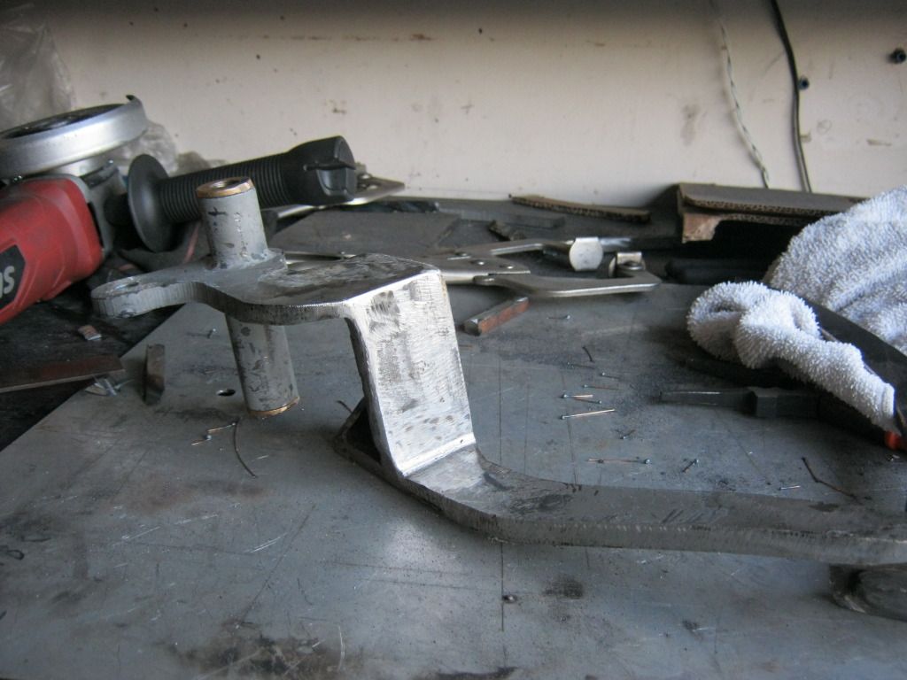
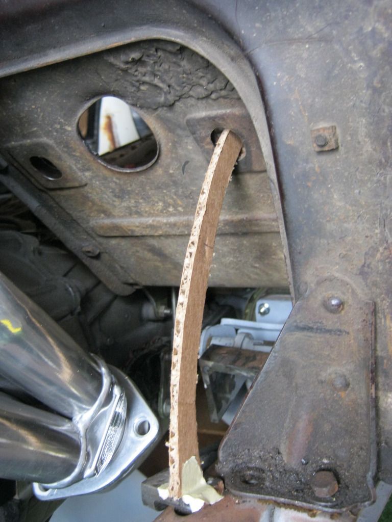
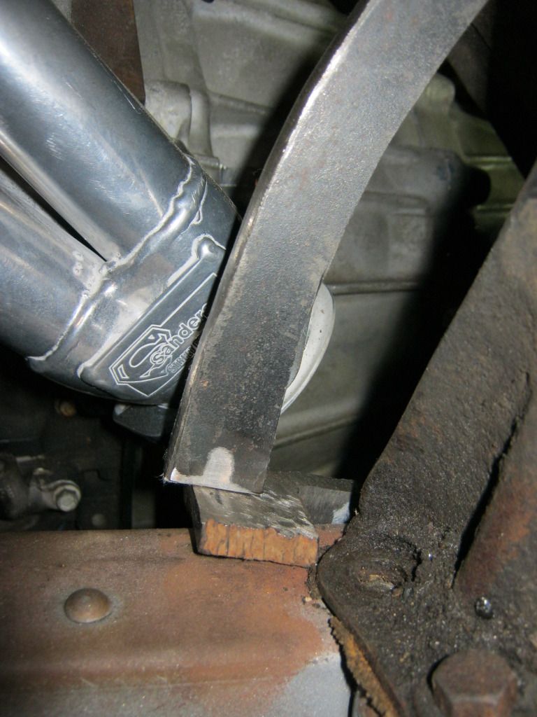
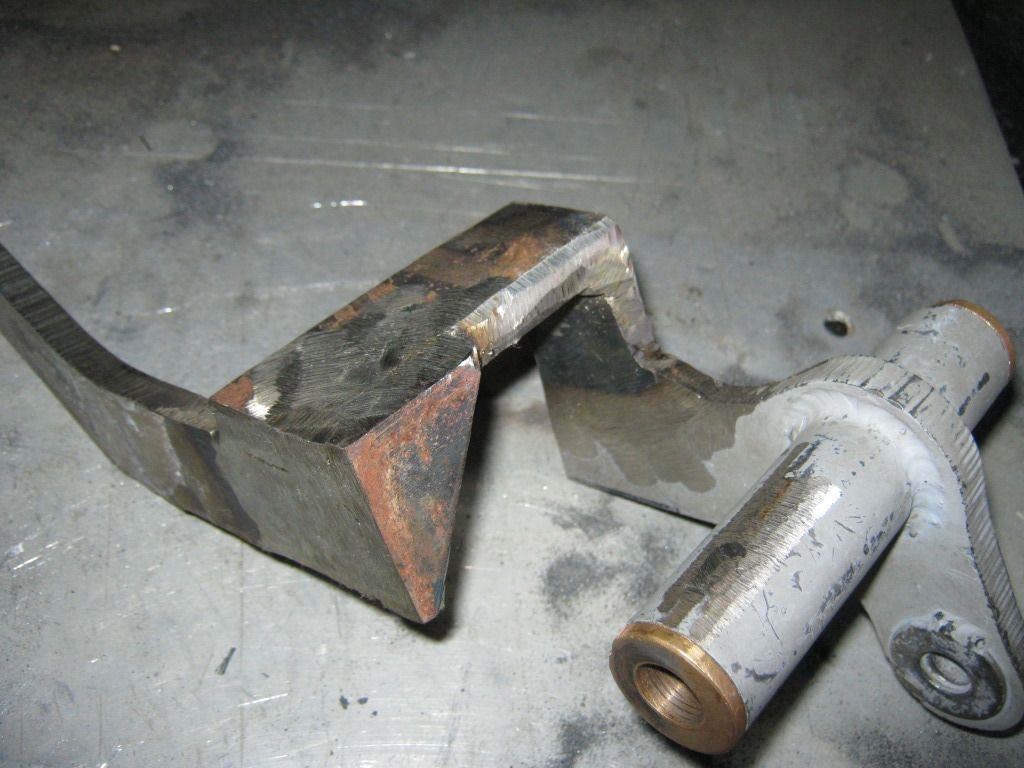
I have been working on this brake arm for the last few weeks now and I'm very tired of it. Because of the tight fitment I have to remove the entire brake arm mount from the frame in order to mount the arm due to limited space, allowing no room for the bolt that holds the arm in place to slide in and out.
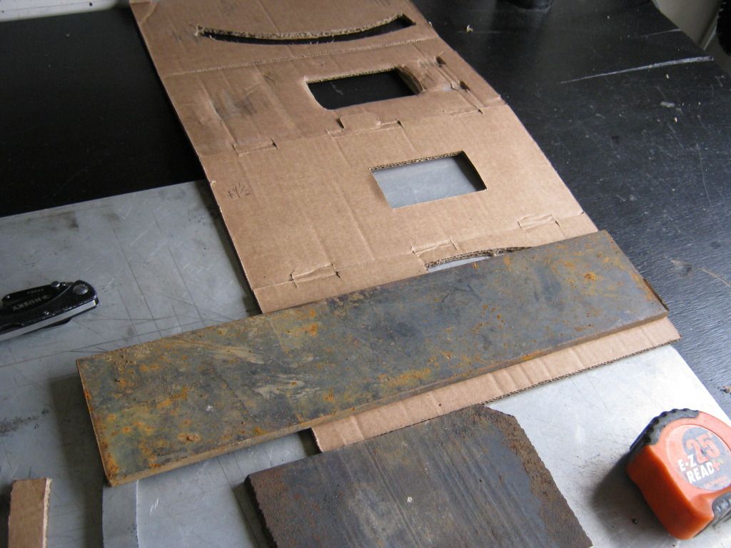
The arc on the arm that goes through the floorboard needed to change so I got a measurement from the brake arm at full bottom and full top. Then I traced the original piece of the arm onto the cardboard.
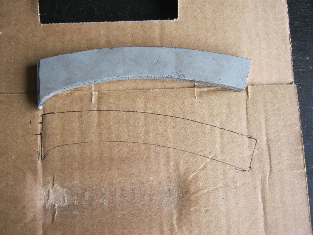
Then I measured how far from the top the piece would need to be moved in order to meet the other measurement. Keeping the straight edge of the piece in line, I moved it down and traced where the other end of the arm would need to be.
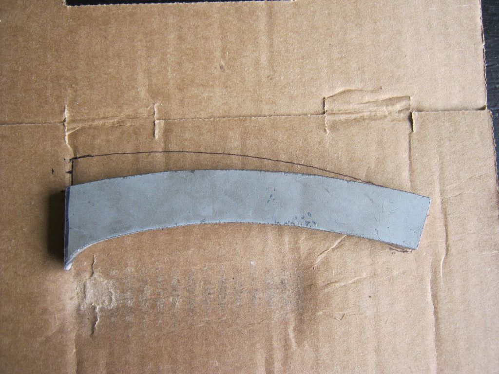
Then I connected the two measurements from the two different locations by using the piece of the arm to draw a curved line between them. I cut out the piece now drawn onto the cardboard. You can see the difference in the arc between the old piece and the new piece.
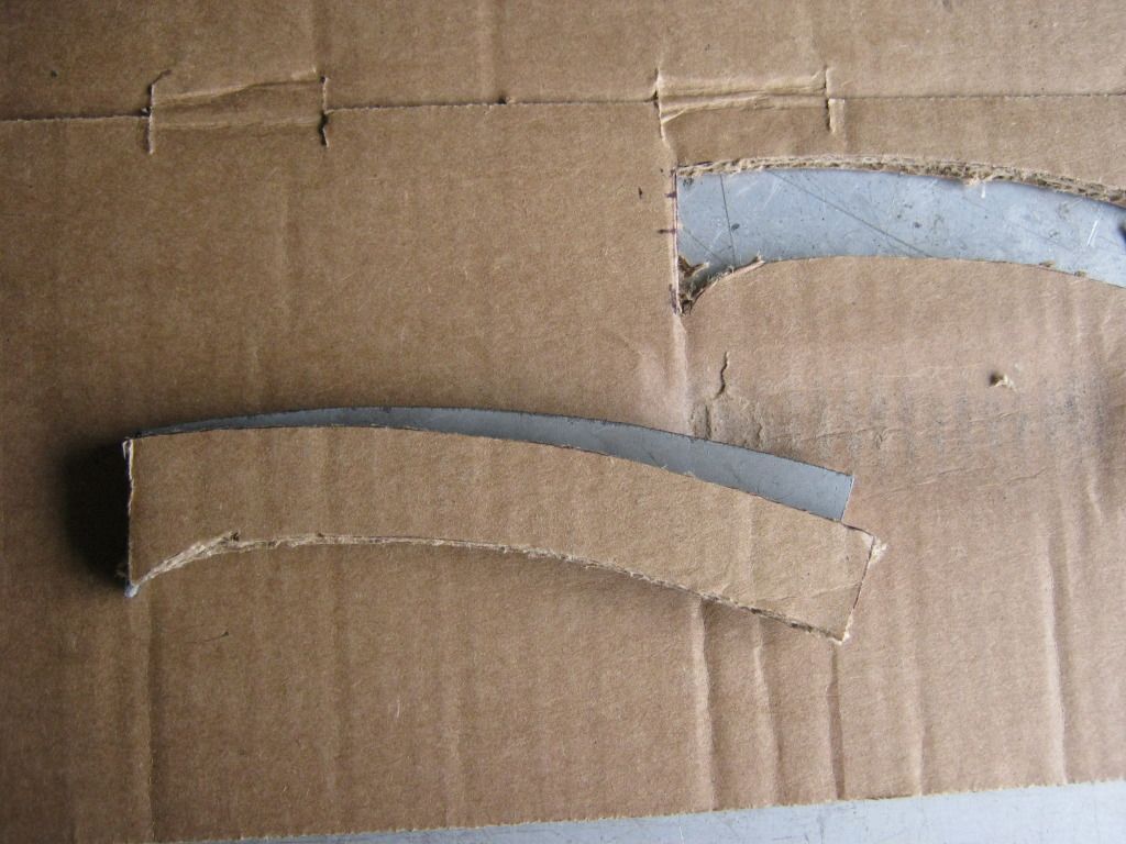
The piece needed to be longer so I used the old piece and aligned it to the edges of the new piece as a reference for making an extension.

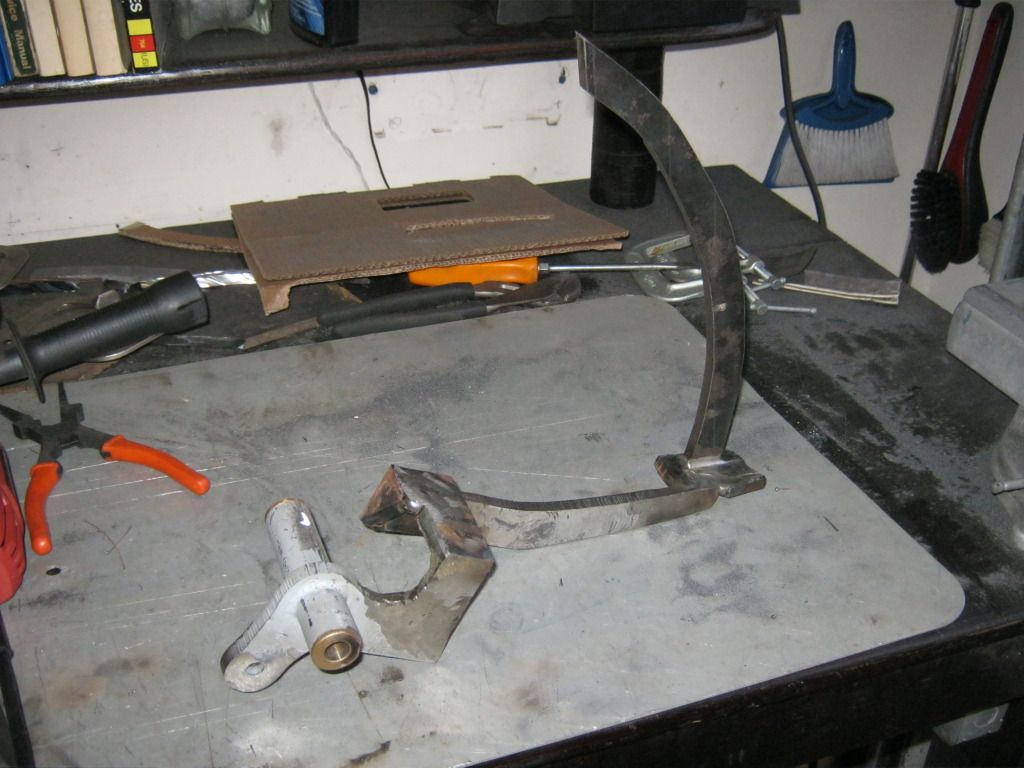
I did a few tests to make sure everything was OK.


The issue I have right now is that there is no brake fluid in the system. This means the brake pedal will depress much further than it will when it is filled with fluid and bled. Because I won't know exactly how much travel it will take at that time I have to make the arm overly long so that I can trim it to the appropriate length after I am in the actual stages of finishing the car and it is filled with fluid. This means the arm will need to be a fairly large piece for now and I don't have any 1/4 steel plates that large, so it's off for another trip to the salvage yard. It had rained that day and it was very messy but after digging around for a while I found a piece exactly like what I needed. When I put it on the scale to weigh it the guy told me to not worry about it and actually gave it to me for free. I needed a piece 13 inches long and 3 inches wide. It's almost as though someone cut this piece just for me.
Then I traced my cardboard template onto the metal.
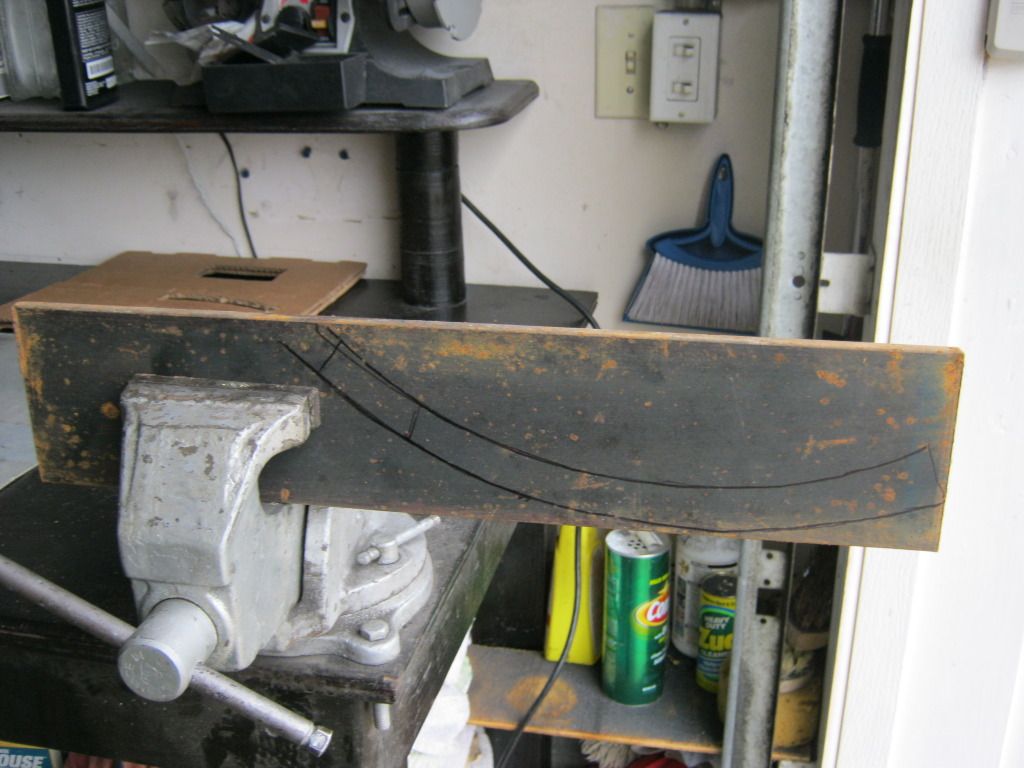
This 1/4 inch steel is some tough stuff and it went through three grinding wheels within a matter of minutes. They're not exactly cheap, either.

Another problem I had is that grinding wheels, of course, won't cut a curved line. By this time it was dark and I had quite a bit of trouble seeing the line I was cutting. I actually cut into my piece in one place.
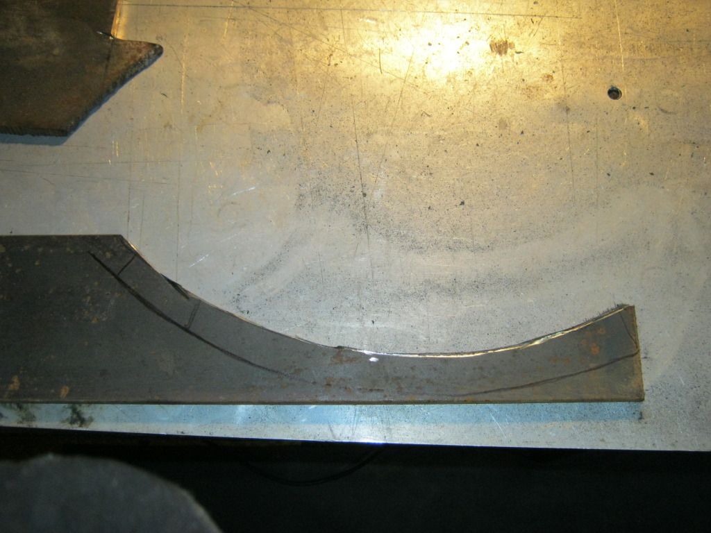
It took a very long time to get the piece cut out and then ground down to resemble the shape I needed. As you can see, it's not exactly a small piece.

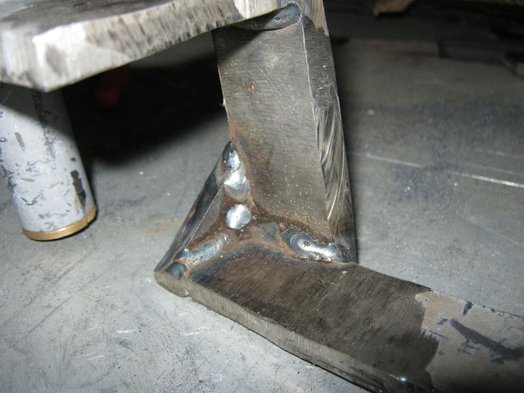
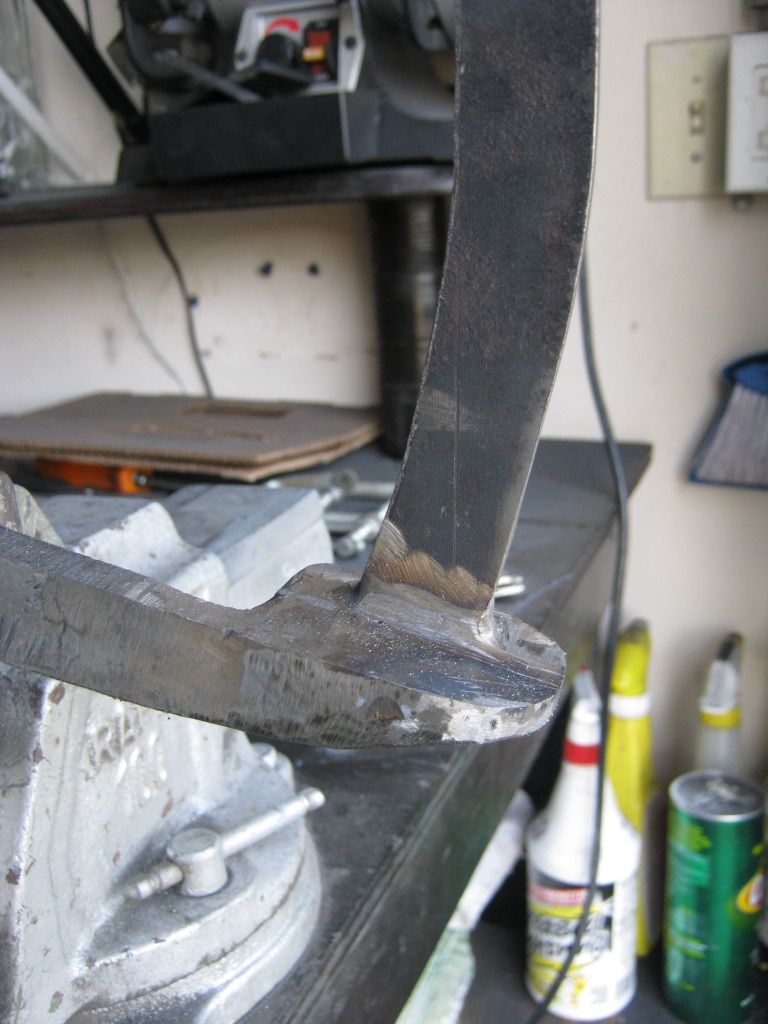
To make sure the angle of the base of the arm was at the same angle as the base it would sit on I used a pen to mark a line. I needed to find the same angle about 1/4 up on the arm so I used an extra piece of the 1/4 steel to make a spacer to copy the line.

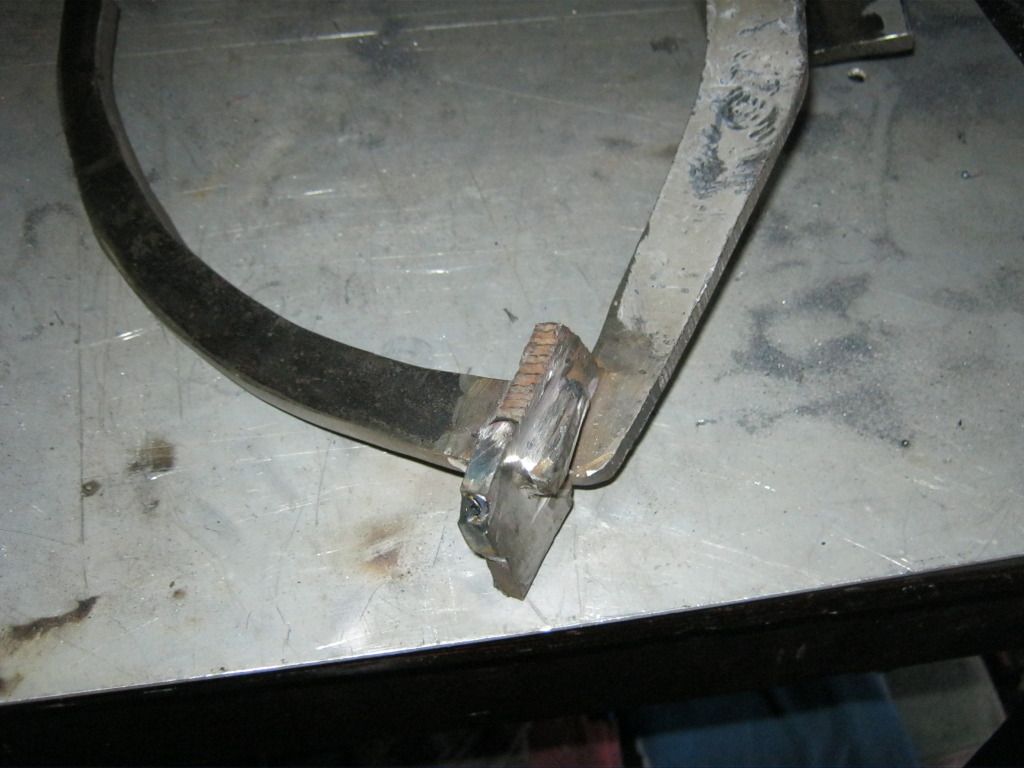
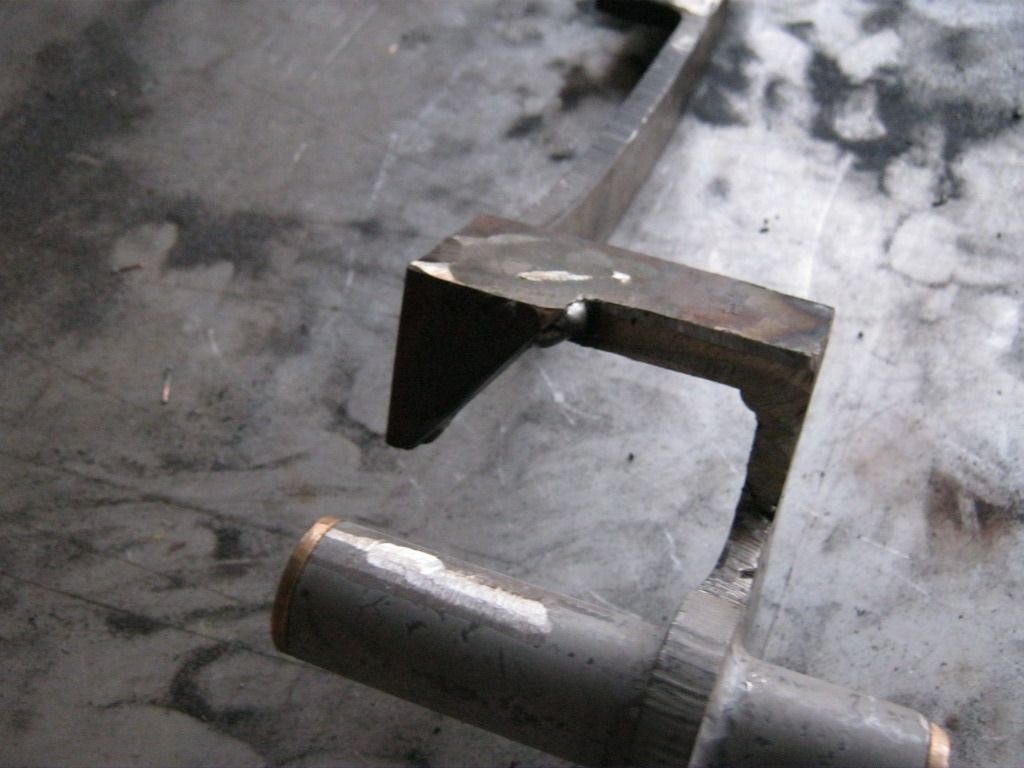
To attach this piece I ended up cutting a notch into the end of the arm slightly larger than 1/4 inch so that the end of the brake arm slightly resembled the shape of a tuning fork. Dad came over and sat inside the car and helped me hold the arm at exactly the right position while I tack welded it in place. Then after fully welding the piece in I cut a very small piece of the 1/4 inch steel and filled in the hole at the top, thus filling in the "U" shape to make the arm fully boxed in.

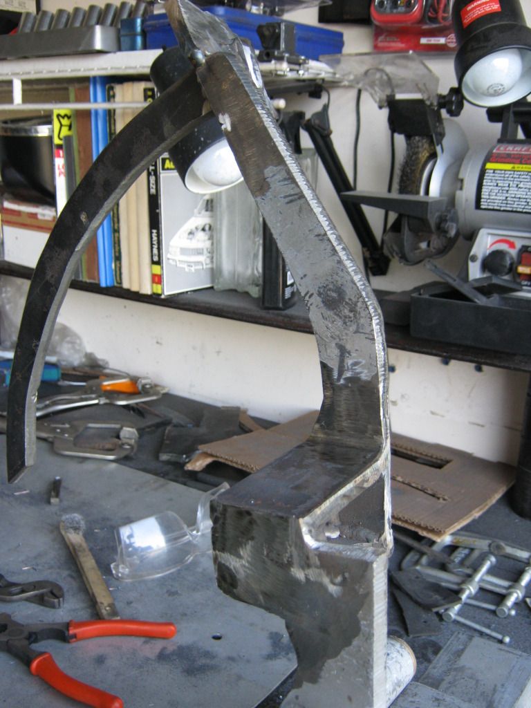
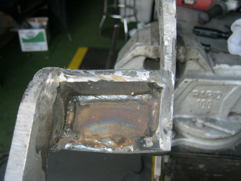
Then began the process of boxing in and adding gussets for strength. This was a long process because each piece had to be measured, cut and then 45 degree angles had to be cut on each side that would make contact so a proper weld could be formed. Then the edges and the welds had to be ground down and then any large imperfections had to be filled in with weld, reground down and then the edges had to be smoothed, rounded and shaped. (Once again, for some reason, the program I'm using to upload these photos refuses to keep the pictures turned the right way, despite the fact I have rotated it back to straight several times)
These interior welds were hard to access and didn't turn out as aesthetically pleasing as I had hoped, but at least they won't be seen.
Then it was time for the piece that would become the front of the box. This piece will add support to both sides of the arm.

I wasn't real crazy about the look of the square angle on this piece so managed to find an angle I liked by breaking one of the old grinding wheels after I had used it up which allowed it to fit up nicely and be used as a template to trace.

I had to cut the corner off and then add some weld in the small area that had no material and then shape it with the grinding wheel. I finished it off with the hand file. This will barely be able to be seen and no one will really notice it, but I liked the look of the curved line better than the obtuse angle.

When it came time to shape up the top I wasn't able to fit anything around the arm sticking through so I had to freehand this shape onto the end.

Switching back and forth between the cut-off wheel and the grinding wheel was time consuming and got very old throughout the project. After some cutting, grinding and shaping it ended up looking like this.
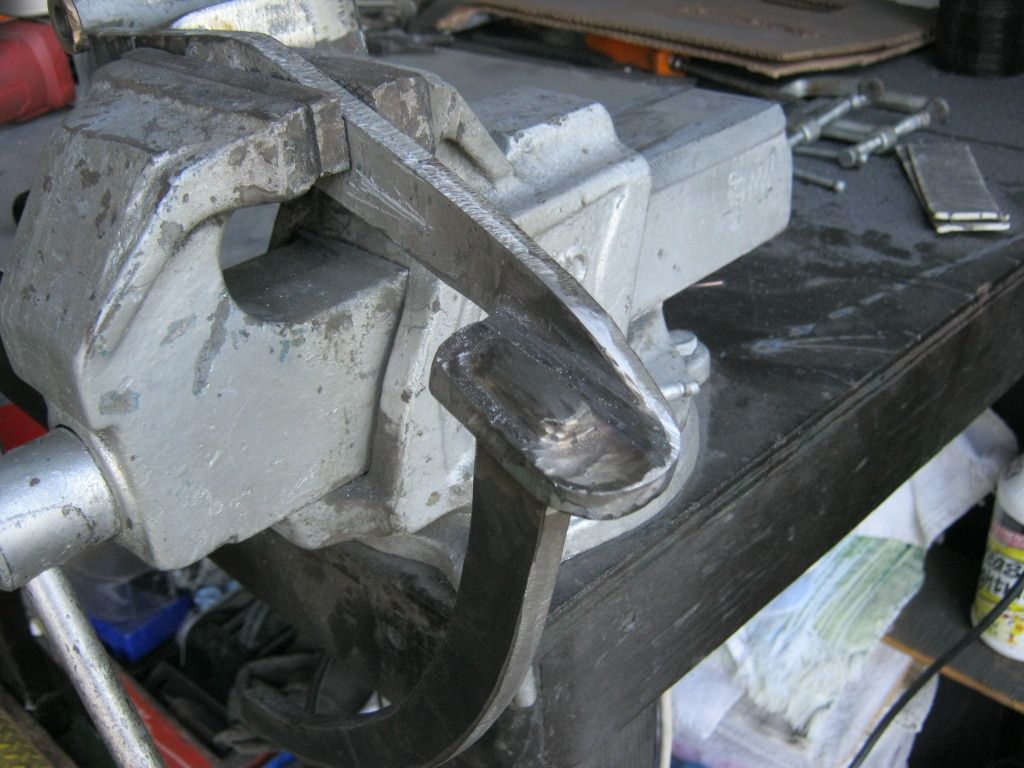
I also added some metal to elongate the arm so it matches the end of the
plate a bit better. I built it up by adding layers of weld and then
shaping them with the grinding wheel and hand file.
The welds inside didn't turn out very pretty, but like I mentioned before they won't be seen.
I had to go back and ad one more gusset I'd forgotten and then I was finished. Tomorrow I'll do a final fitment and hopefully the welding hasn't pulled the arm too much for me to straighten back out.