Tuesday, December 25, 2018

The Firing


Another bout of weather and sicknesses in the household prolonged progress yet again.  I also had to divert some attention to some issues with the Lumina which had to be fixed. 

There was a plastic tab on the mass air flow senor that apparently fit into a grove to clock the sensor in the correct rotation on the original application.  Here, it prevented me from clamping down the MAF sensor straight.

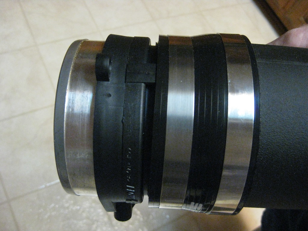
I used the dremel and ground the tab off.

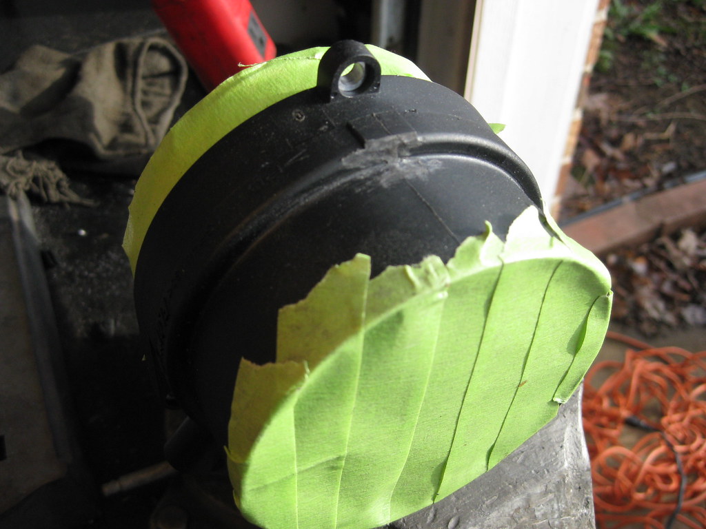
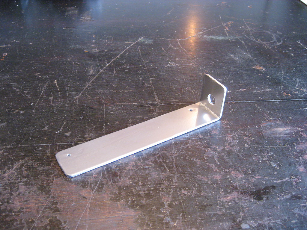
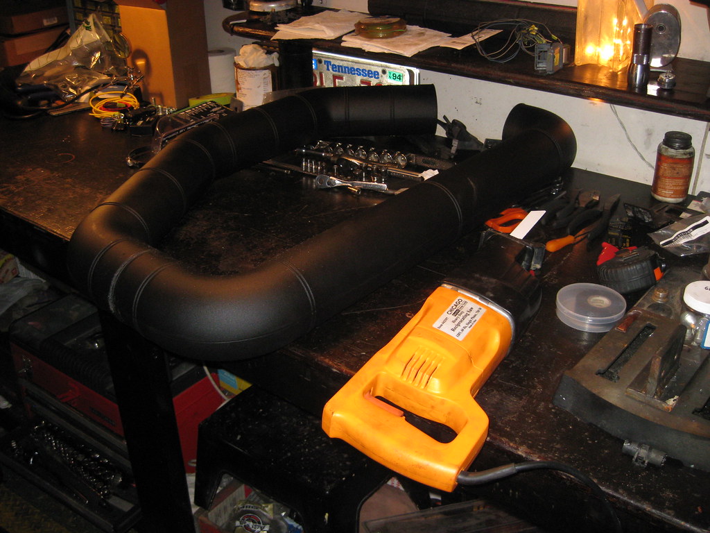
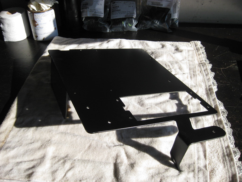
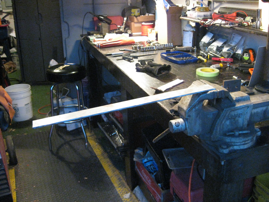
I also needed to make a bracket to support the filter end of the intake.

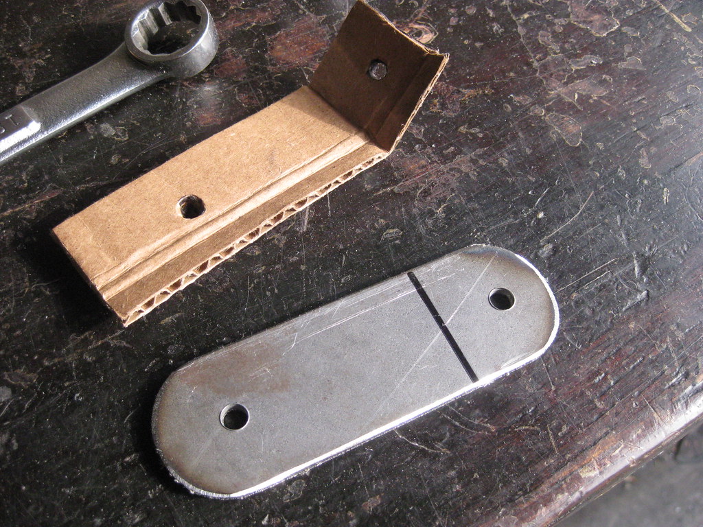
I remembered to drill the holes prior to bending this time.

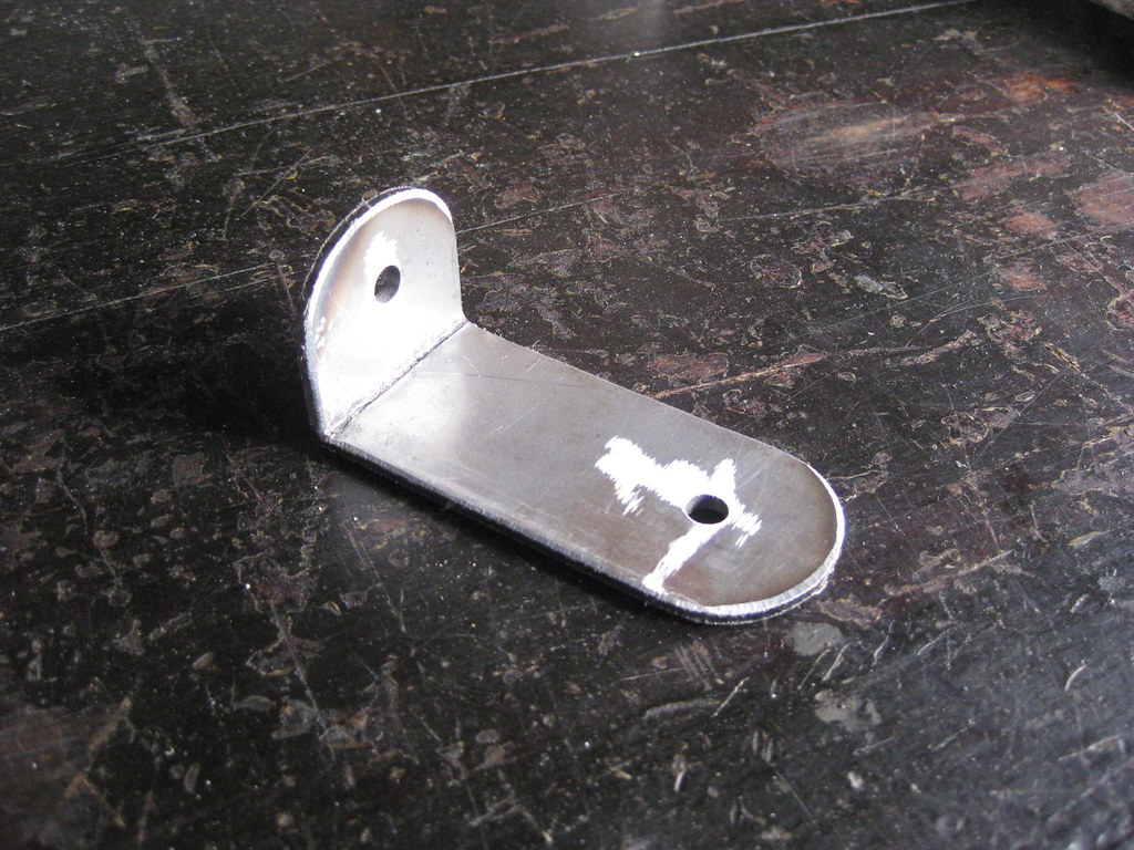
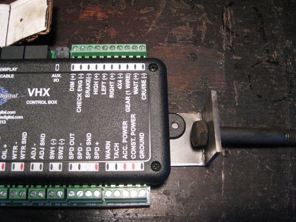
The bracket ended up looking like this.  I have yet to paint the bracket in the pictures below.

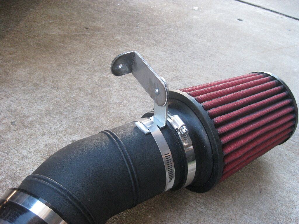
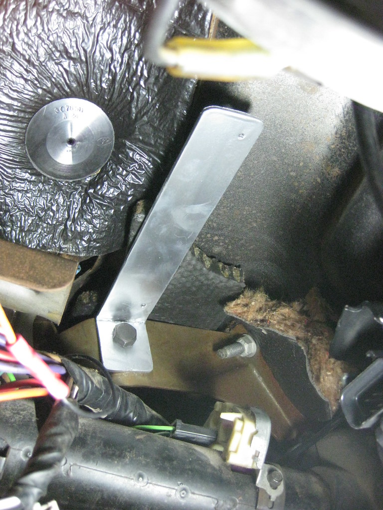
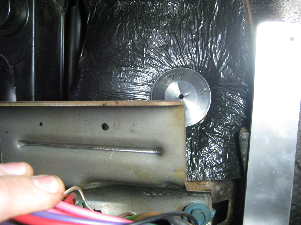
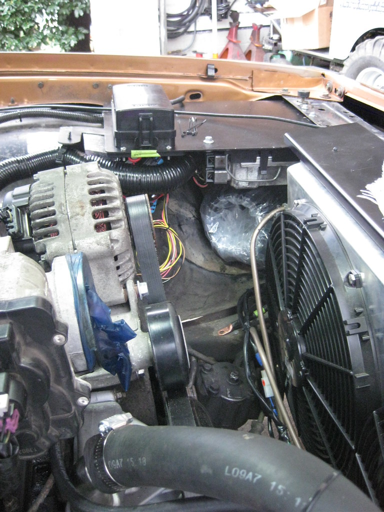
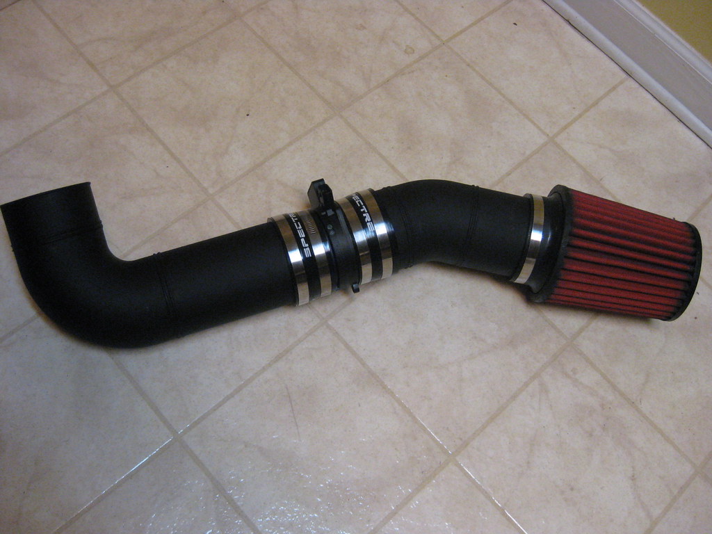
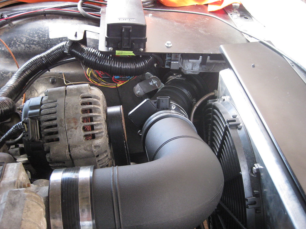
The intake setup ended up like this.  The filter is positioned under the fuse and pcm panel.  I later plan to block off the side of the panel to create an airbox.  I need to find out how much heat the pcm put off to make sure it won't heatsoak the intake.

The day I finished up the wiring under the dash it was very, very cold.  I had several layers of clothing and coveralls on, so it was really difficult to lay in the floor and reach under the dash to work with the wires.  Also, the metal floorboard was so cold it would come through the layers.  There was  a Christmas parade that day and I wanted to be there with the girls so my workday got cut a little short.

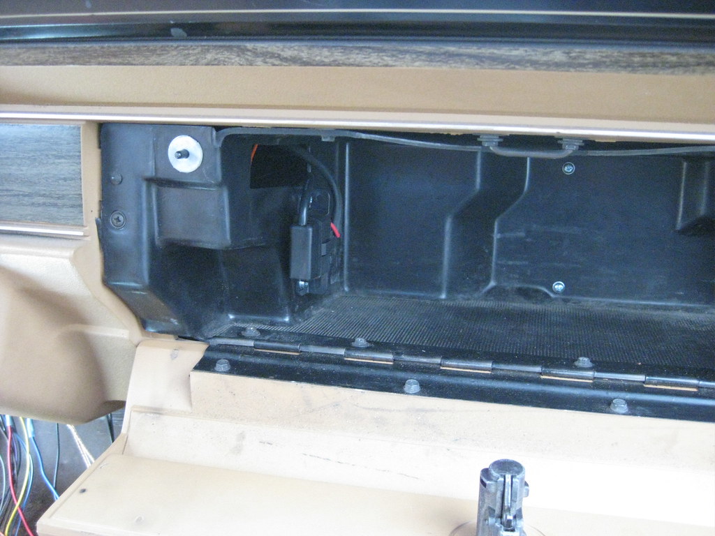
I took the glove box out so I could mount the OBDII port.  The wire for the glovebox light was barely hanging on and it broke off when I removed it so I soldered it back in place.

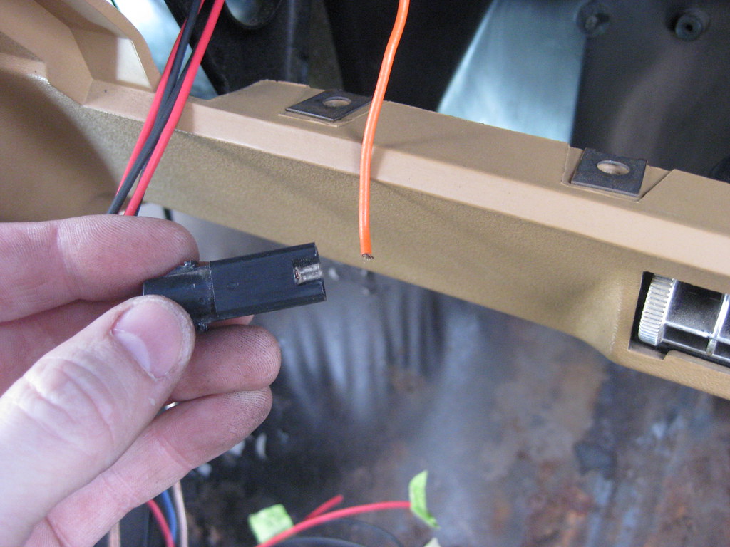
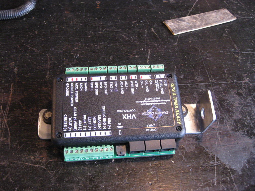
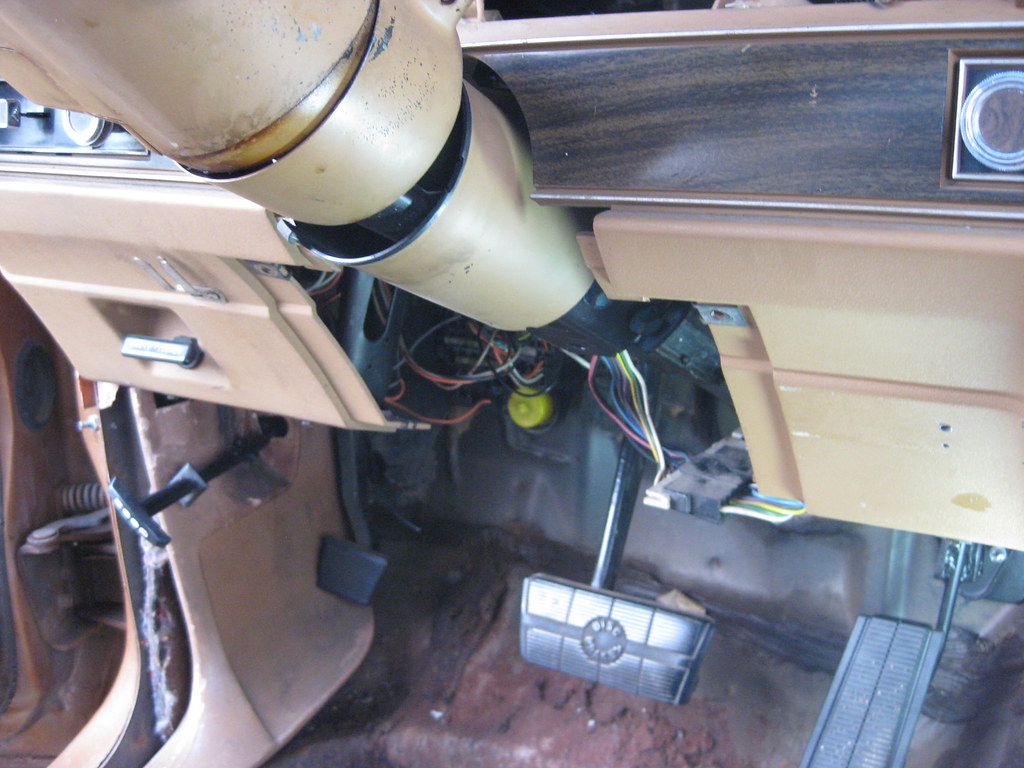
Fortunately there was already a large hole in the glove box so I routed my wires through that.  Here I'm finding the alignment of the holes to be drilled.  I also mounted the Dakota Digital OBDII box on the back of the glove box which is not shown in the picture below.

This is where I mounted OBDII port.  The two screw heads on the back of the glove box is where I mounted the OBDII controller.

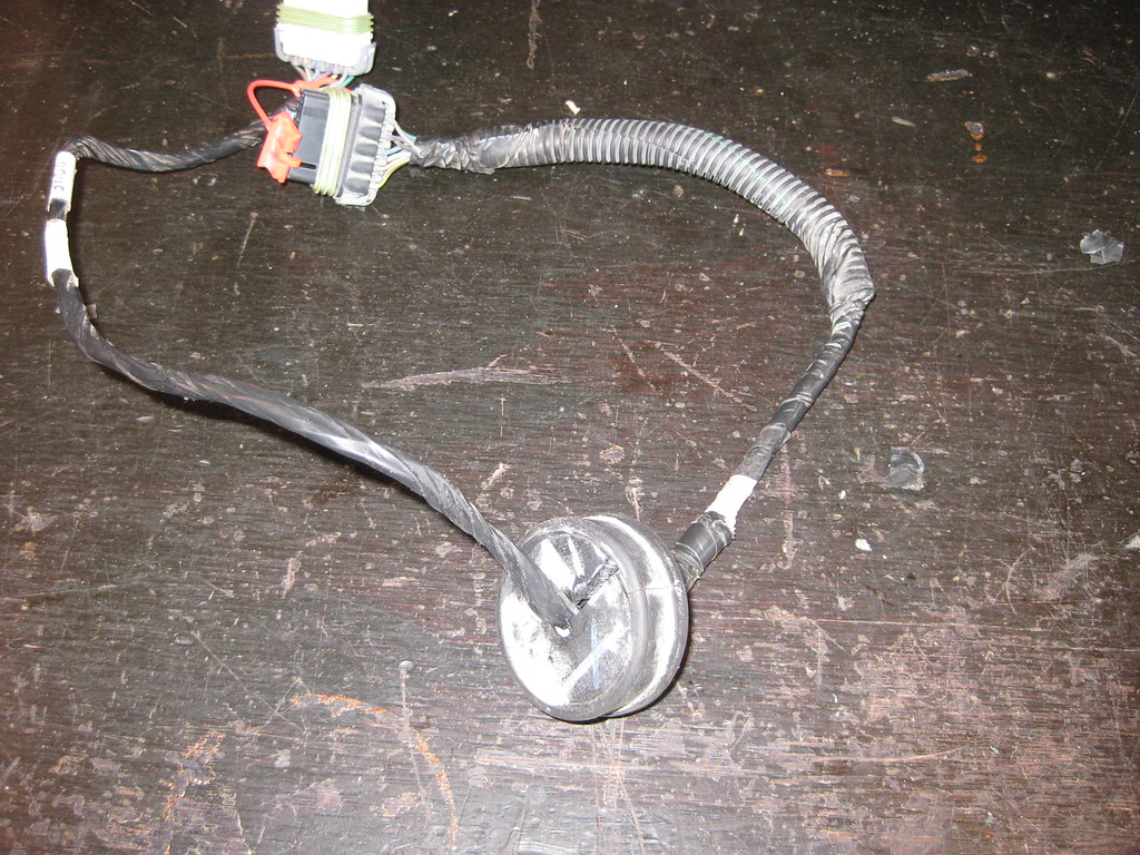
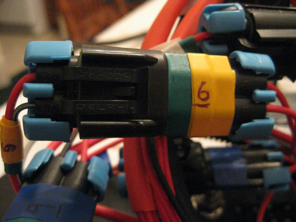
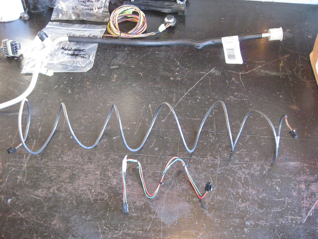
The harness that connects the Dakota Digital brain box to the OBDII controller wasn't long enough so I had to order a longer one.

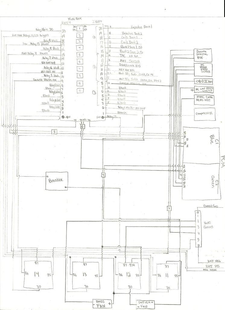
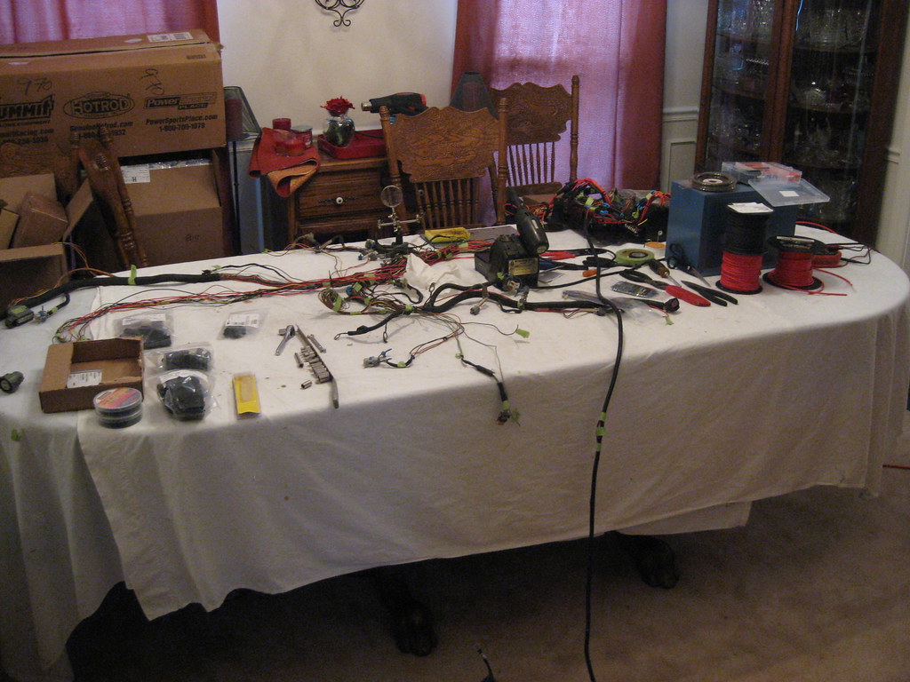
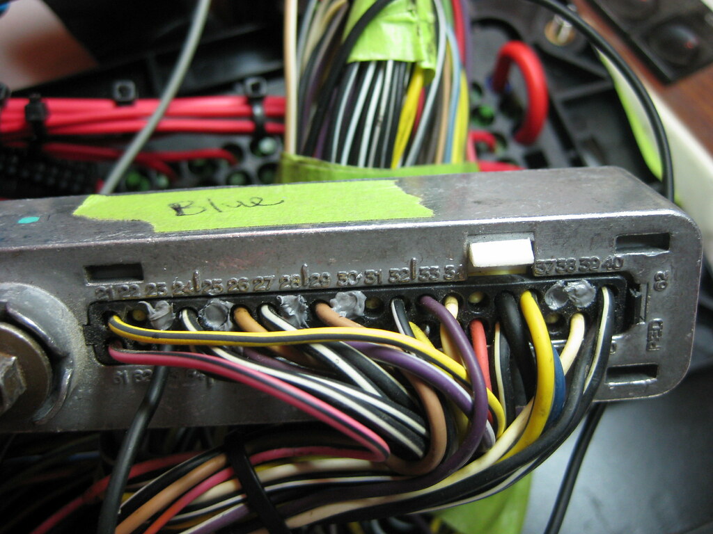
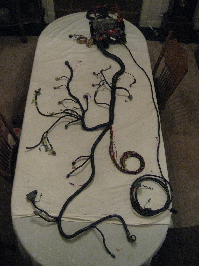
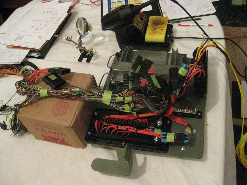
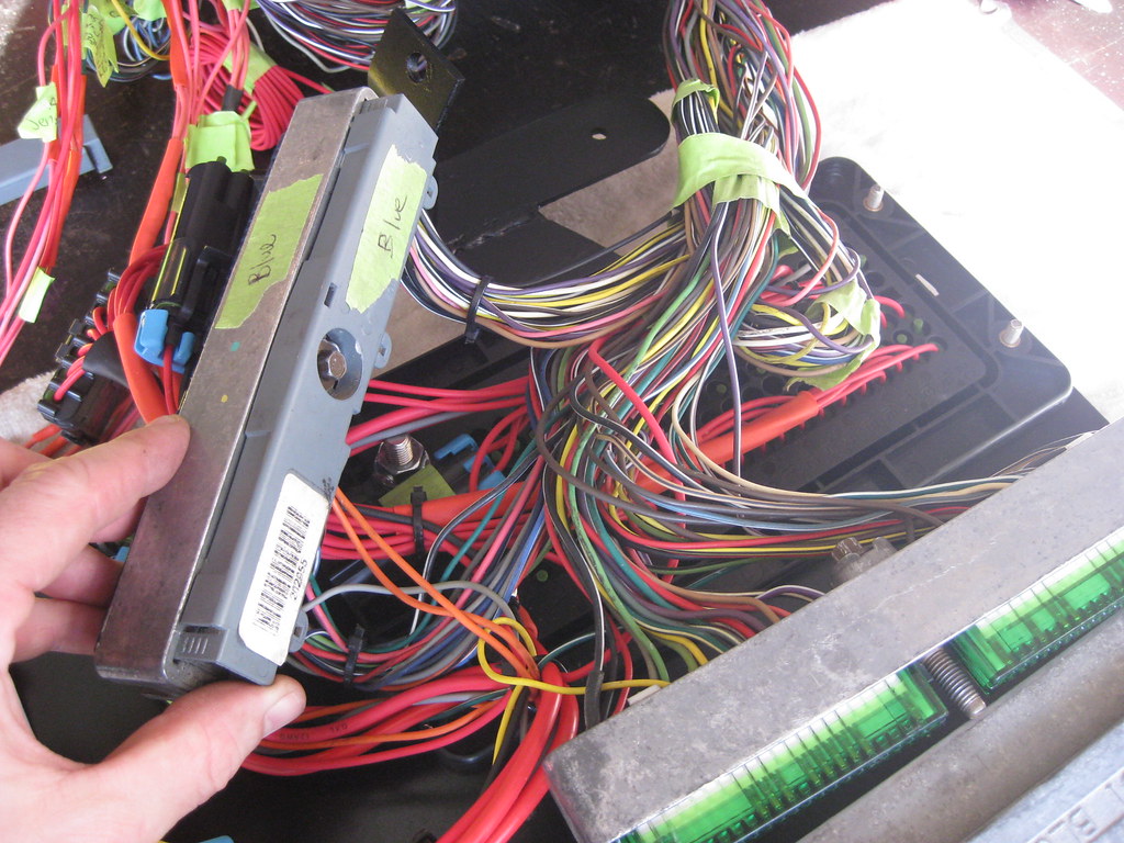
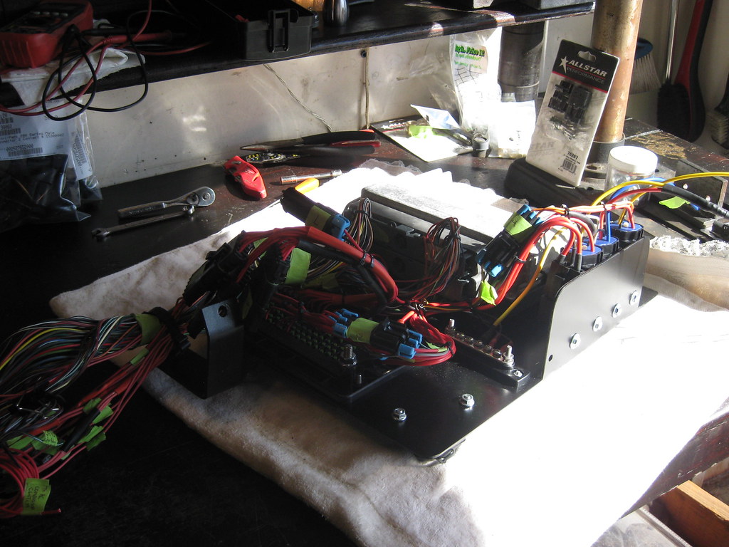
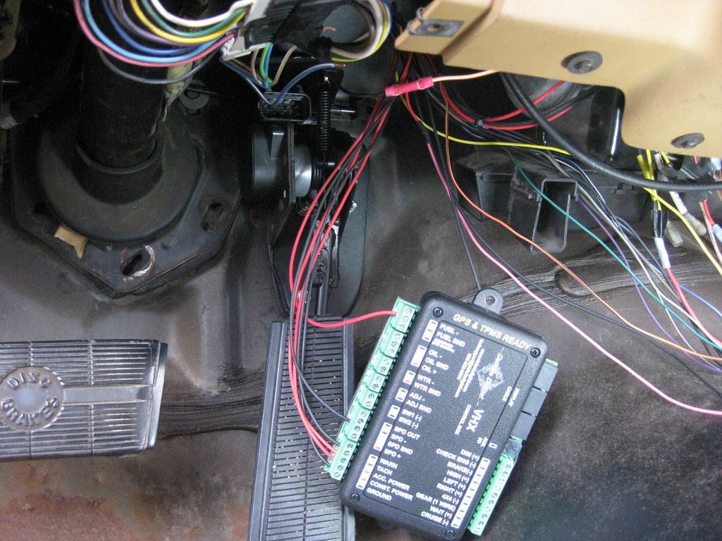
I had previously made a diagram of where each wire should go and used the 1978 Caprice wiring diagrams to determine which wires I needed to splice into, which made finding and hooking everything up much quicker.

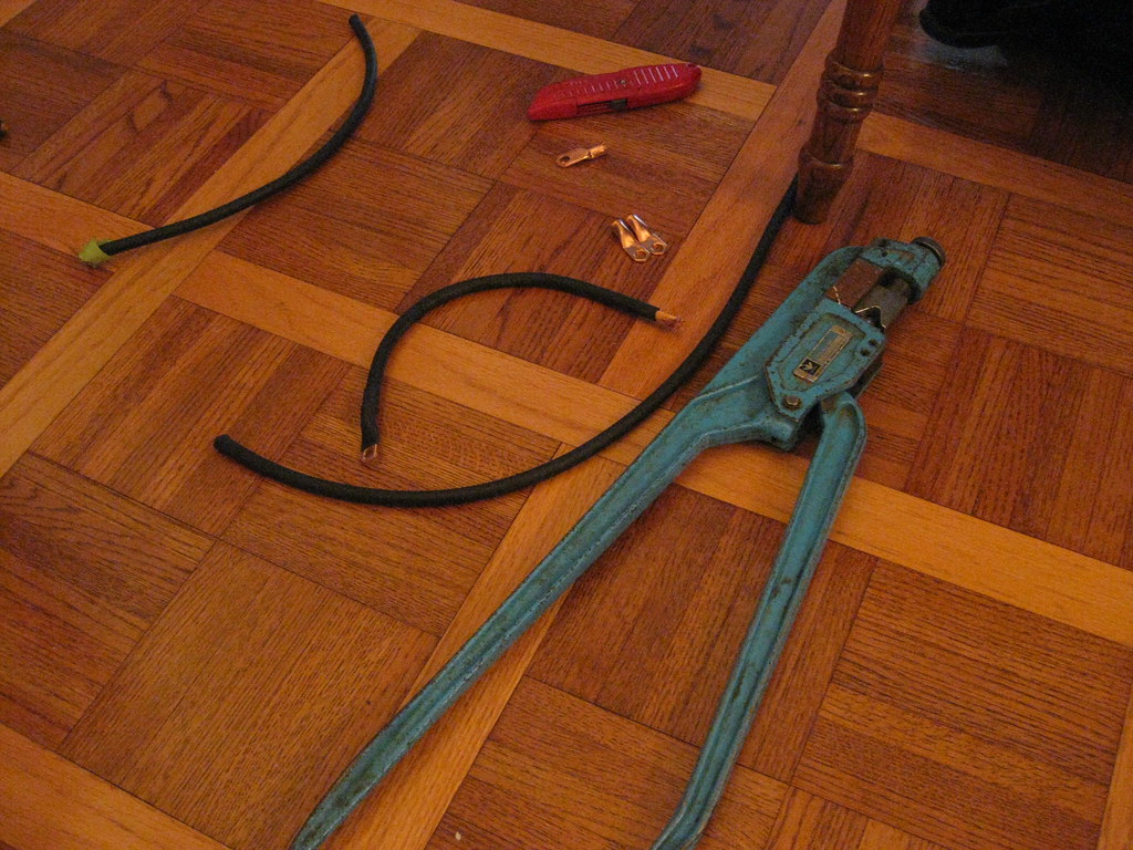
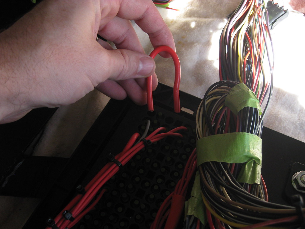
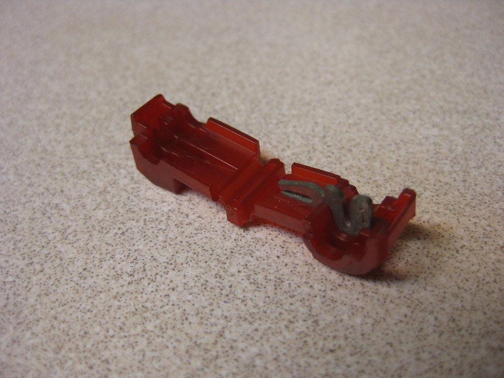
These are T-clamp wire splice connectors.  This was the first time I've used them and I really preferred them to the previous kind I had been using.  I actually didn't even understand how to use them at first.  You just clamp this onto the wire you need to splice into and then insert a blade connector into a small hole in the folded over end, that way you can disconnect the splice if you ever need to.

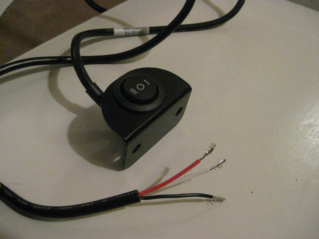
The instructions with the Dakota Digital dash were a bit confusing and caused some delay.  In short, Dakota Digital used to provide two push button switches with their units that each had two wires.  Now they provide one rocker switch that has three wires and has two functions, up and down.  The wiring diagram has been updated to reflect this change, but the written instructions have not, so they were conflicting.  Also, Dakota accidentally sent me two separate switches and they were only supposed to send me one, so it was very confusing trying to find out how everything was supposed to be wired.  I called the company and we finally worked out the issue.

At long last it was time to install the cluster.

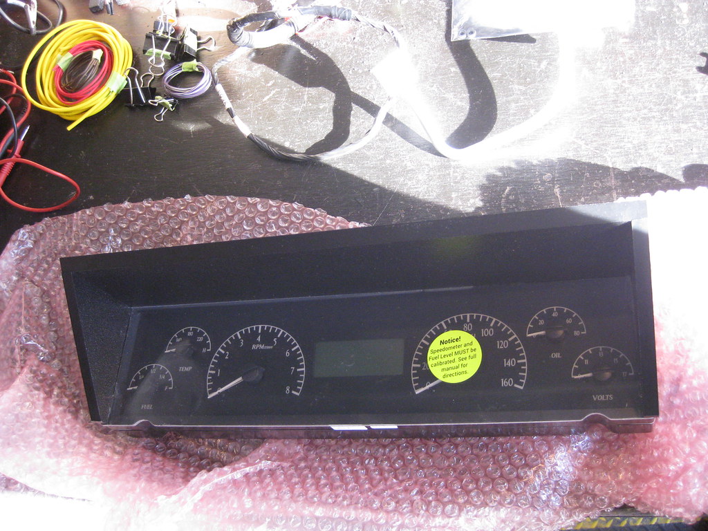
There are only two bolts that mount the cluster to the dash so it was a pretty straight forward and easy install.  The stock lens installs over the top of what is shown below.  My original lens was in poor shape with some of the tabs broken off from various people working on it over the years.  Over the Christmas holiday I went up to the farm where I have a parts car in the barn and I got a lens that was in better shape.

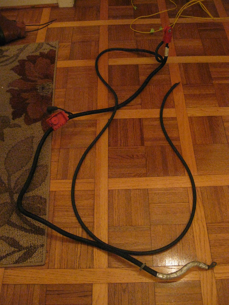
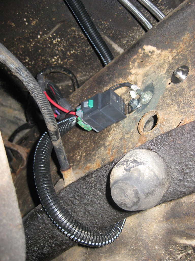
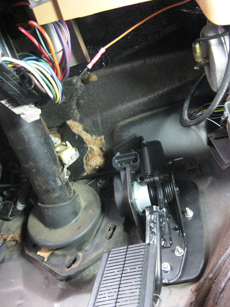
I finished connecting the remainder of the wires.  I attached the battery negative cable where the compressor was mounted on the 5.3.

I used some of the original clamps to route the cables.

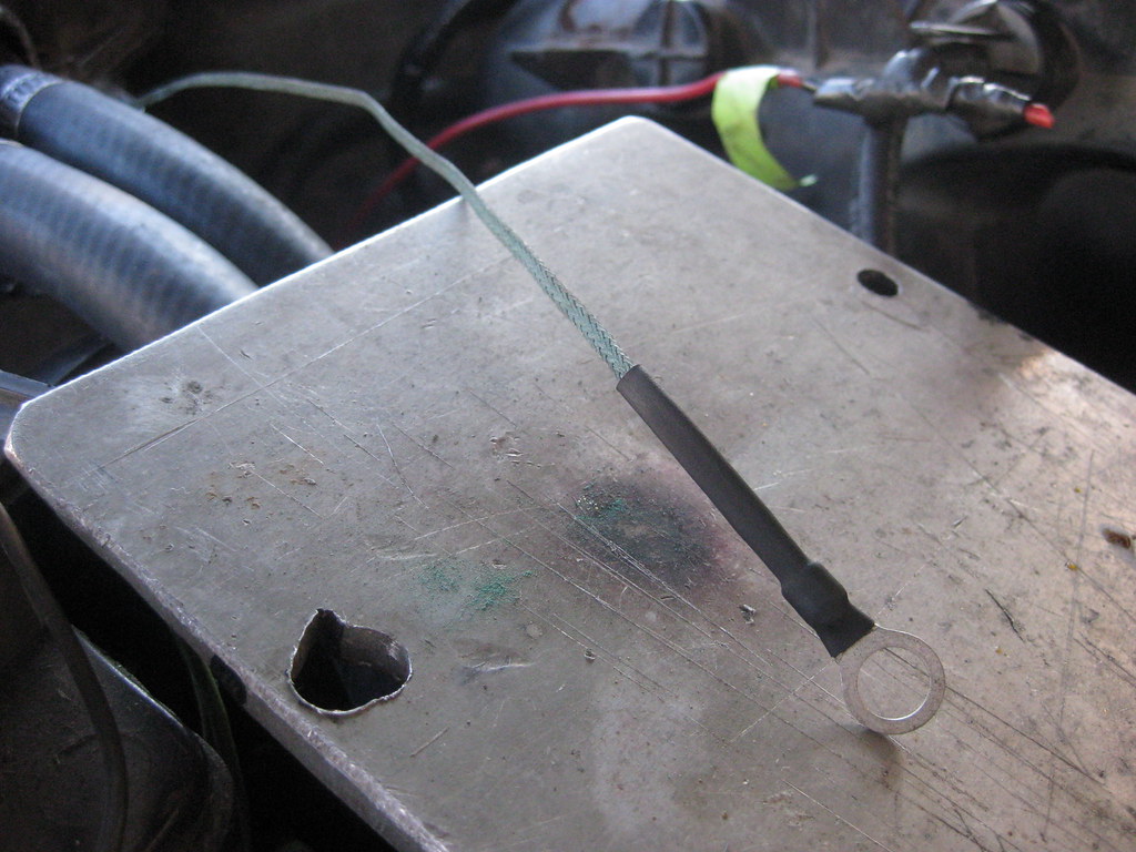
I finally fixed the broken ground strap that came out of the heater core box and I also cleaned up all of the ground mounting locations with a wire brush dremel.

I still had some soldering that needed to be completed on the car.  Now that the air intake system was complete I could determine how long the MAF sensor wires needed to be and also some of the wires for the AC sensors and switches.  My father-in-law was in town for the Christmas holiday and helped with soldering all the remaining wires on the car.

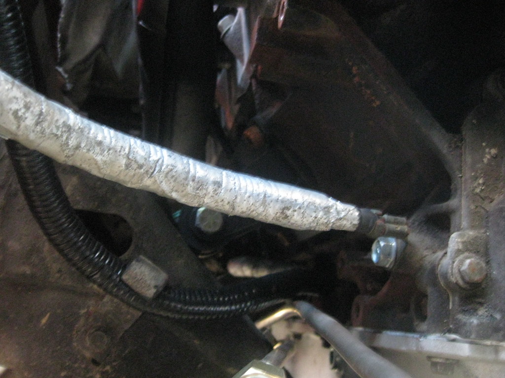
I got the AC hardline rebent and installed.  I had an issue with installing the accumulator and I essentially ruined the threads to the evaporator.  I'll most likely have to install a new evaporator and get a new accumulator, but all that will have to wait until after I get the car running.

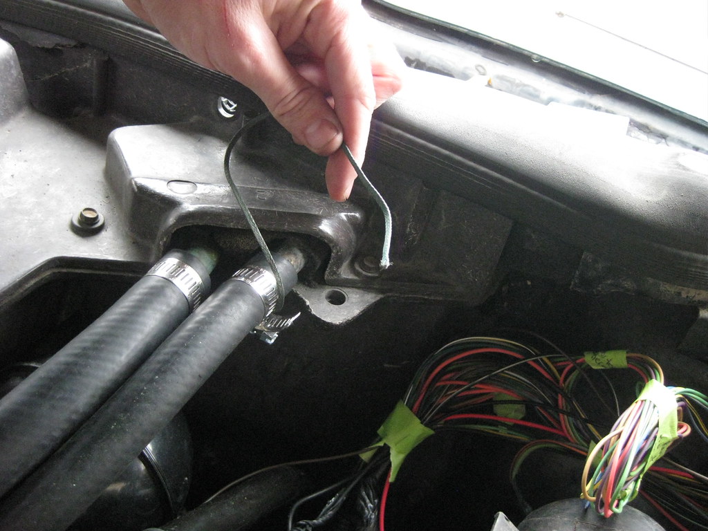
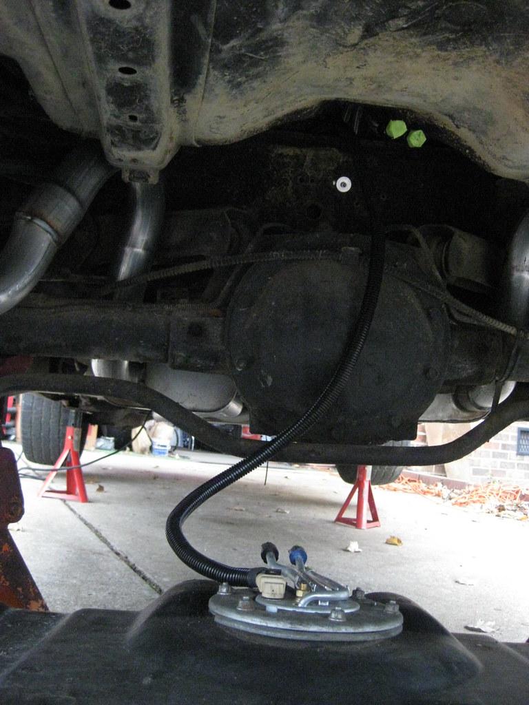
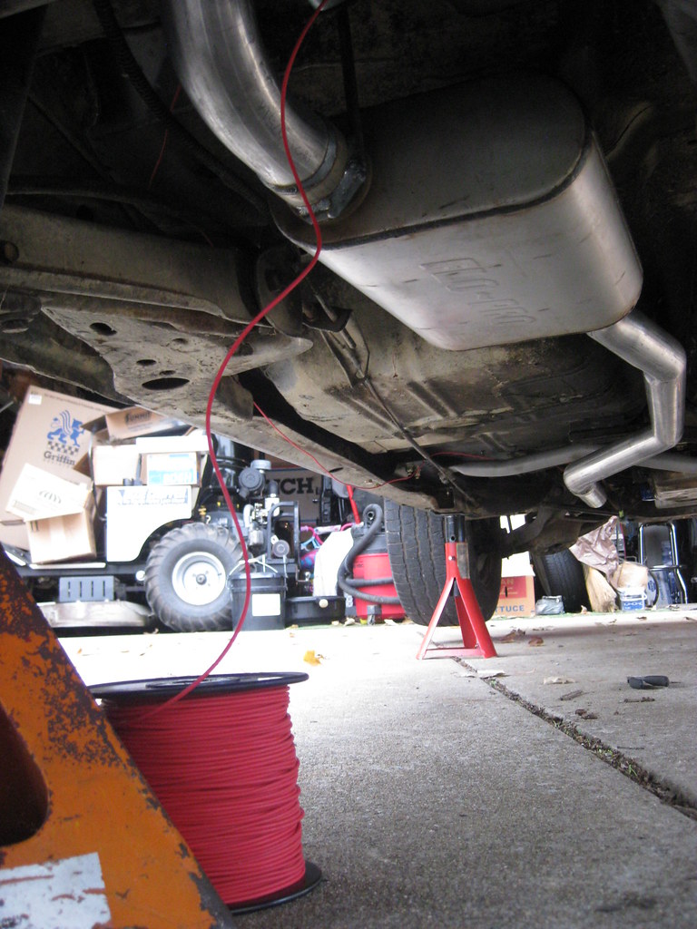
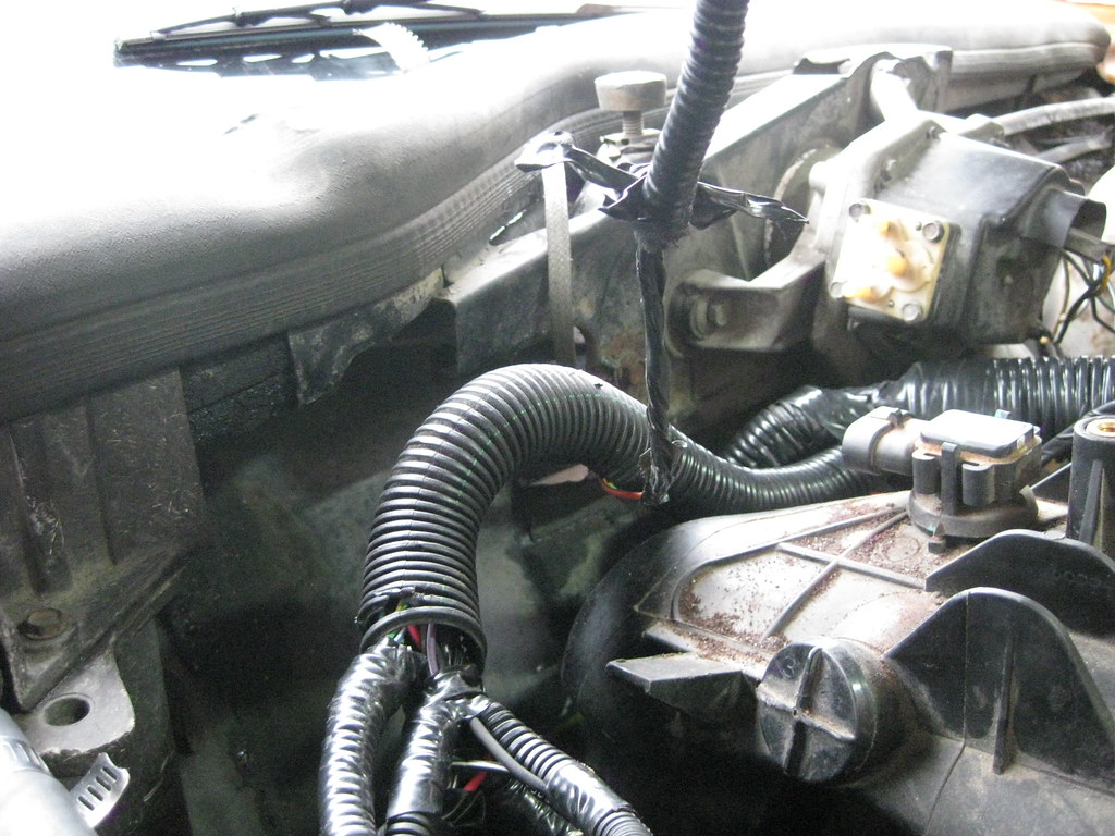
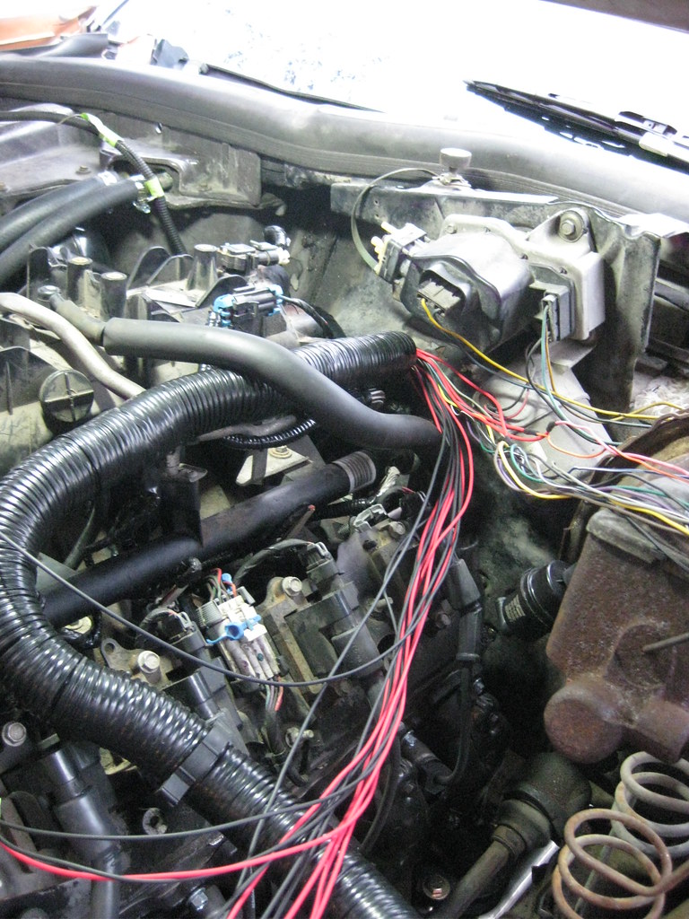
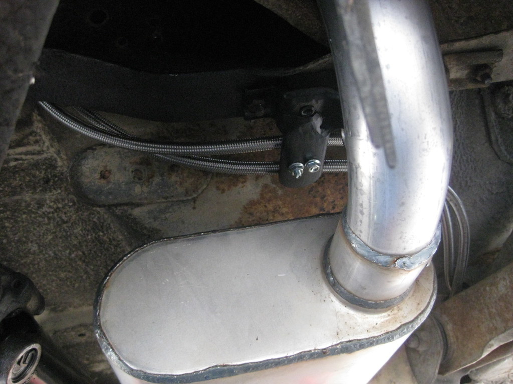
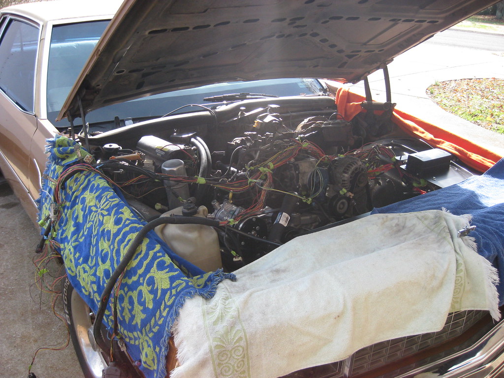
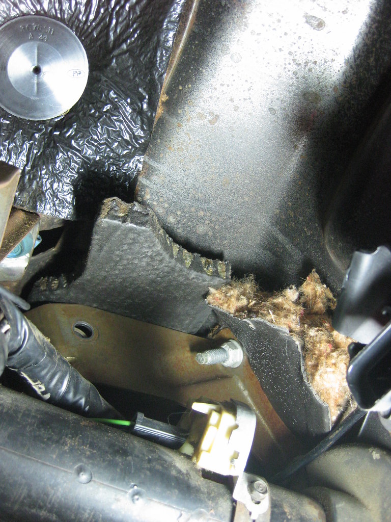
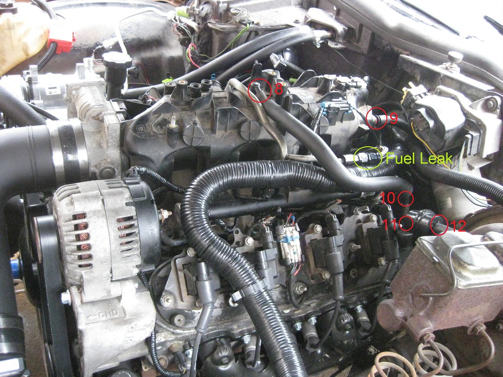
Before I started the car I wanted to get the dash working so I would have gauges to monitor.  At first the dash wasn't working but then I later realized I had put some of the fuses in the wrong location.  I left some gaps in the fuse locations that can be used to power future relays if I chose to install them.   When I put all the fuses in I forgot to include the gaps.  I was finally able to start the engine after putting some gas in the tank.  I could hear the fuel pump working and the engine didn't crank over very long before it fired up.  It is way louder than I wanted so I'll have to take it back and get quieter mufflers put on.  When the engine started there was no response from the gas pedal.  At the very beginning the engine would idle around 800 rpm, but now idles around 1250 rpm.  I was scared at first because when I first start the car it will quickly rev to 2000 rpm and after a couple of tries I found that once it gets to 2000 rpm it will come back down to 1250 or so.  I was also getting a code for a MAP sensor.  The probable causes for this seem to be a vacuum leak, but I have yet to find a leak.  Below are all of the places I've looked to try to find a vacuum leak.

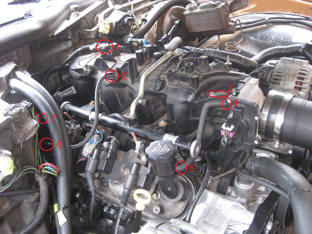
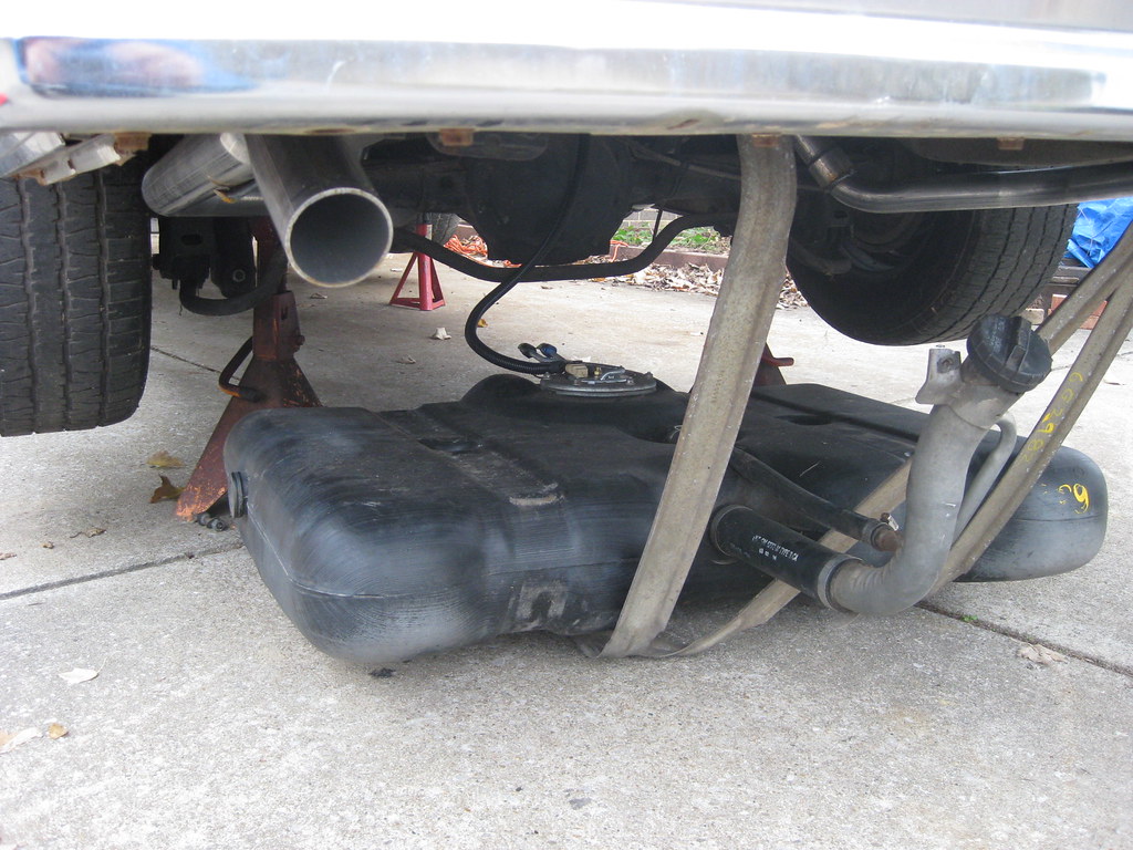
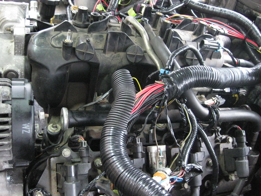
I also had a small fuel leak.  I tightened the connector marked below and it so far seems to have eliminated the leak.

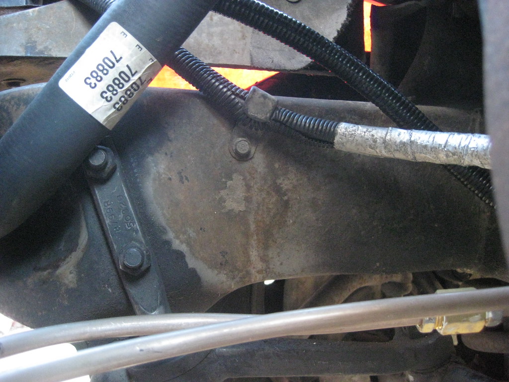
I filled the upper radiator hose and then filled the radiator and there appears to be no air left in the cooling system, however the engine slowly overheats.  I also noticed after letting the engine run for about two minutes that the exhaust manifolds were glowing red hot.  Given the pedal having no response, the glowing manifolds and overheating it seems as though it would be best to have a computer hooked to the computer to see what's going on with the tune before I go further.  The PCM is a 2003 Express Van tuned with a 2004 Tahoe tune.  With the Holidays here I am somewhat stuck until I can get a tuner hooked up and see what's happening.


Tuesday, December 4, 2018

Spaghetti Factory

So much time has gone by I've lost track of where I was in the progress of the build.  I had some vacation days so I took a couple days off and worked on the car from almost sunup to late in the night both days.  Since I want to be able to work on this car and diagnose problems later I made a first draft of a wiring diagram.  I've since added some new things that I'll have to addend on the second draft, but I knew if I didn't draw it out while it was fresh on my mind I would probably forget some things.


I have a lot of extra spray paint cans that I rarely use taking up some much needed space in the cabinet.  That means the bracket for the Dakota Digital box that will be tucked up way under the dash and never seen will be..... chrome.  There's still a shifter linkage bracket on The Camaro that's bright gold that no one will ever see.

I used the bolt for the brake pedal arm to locate the mount.  The Dakota controller will mount here, over the top of the steering column.  It's also close proximity to the hole in the firewall so the wires won't have to be very long.

Next I mounted the electronic pedal controller.  There was a good place to mount it on a bracket that was already in place.  After finding a good place for it to sit I made a template out of cardboard.


And marked where to drill the holes.  Fortunately, the drill easily fit into these locations.

The pedal controller box originally mounted under the hood on the Avalanche.  I'm mounting the box inside, so it will plug into the pedal and go straight to the box.  I removed the old firewall grommet, which could seemingly double as an escape hatch on the Avalanche.

I thought I was going to have to make a trip to the hardware store to get some self tapping screws and then The Caprice provided two screws exactly the right size, and they were self tapping, right there in the glove box as I cleaned it out to find a place to mount the OBD connectors.  It seems after all this time she's finally come around to being cooperative on this build.  I used them two mount the Dakota controller to the mount.

I think this ground strap broke during the engine installation.  I'm going to reattach it to the body where it goes.

I dropped the gas tank to install the fuel pump and sender harness.  Hopefully, this will be the last time I have to install the tank.

I hooked everything up except for the fuel tank vent, which I am still considering as to what route I want to take there.

I used a single wire to measure how long all of the wires would need to be to run back to the fuel pump harness, finding a good path down the frame rail and up to the fuse box.  It was time consuming installing and uninstalling and using green tape to make notes about where wire loom and connectors should go.

Then I cut the other wires to fit.

Then it was time to test fit the harness.  I had, at long, long last, finished up everything on the harness I could without putting it in the car and measure how long some of the wires needed to be.  I used green tape to mark where the wires would need to exit the loom so when I wrapped it in black tape they would be in the correct location.  I ended up using just a few long wires and then marking them with green tape to indicate how long certain wires would need to be, then when I took the harness back inside I would measure a new wire the length it needed to be with where I had marked with tape on the test wire.  For example, I had a mark to indicate how long it would be from the PCM connector, inside the cabin to the Dakota Box, or OBD connector, or how long to the AC components, etc, following the loom.

Then I once again made base camp back in the dining room.

I had a pretty frustrating time at the local electric shop.  I had measured exactly how many and how long I needed each wire to be for the battery and ground wires.  In a story that's too complicated to explain, I ended up having to cut my own lengths with tin snips and I pieced together enough of the correct size lugs from several different stores to complete this part of the project.

I had to rent this tool to crimp the lugs on the wires.  This tool and I spent some time together a few years ago when I had to rewire my lawn mower.

The original battery cable had a lead coming off of it that went to the fuse box.  I spliced the wire with a huge barrel connector and crimped it with the rented crimper and extended it to reach the fuse box.  All the connectors got heat shrink tubing.

The original unused ports on the PCM connectors had rubber stoppers in them.  I used RTV to cover the holes to prevent moisture and dirt from getting inside for the slots where I removed wires from the harness.

I finished up all of the electric fan wiring and various components and connectors so everything can easily come part if ever need be.  I then color coded all of the connectors on the fuse box so if I ever take them off I can tell which ones go back together.  Green and yellow goes with green and yellow.  Hopefully even I can figure that out later down the road.

After what seemed like endless soldering, the harness was finally done.... almost.  I actually rubbed my hands raw from installing the looms.

There were a couple spots where I didn't exit the wires in the correct location on the harness and I had to cut the tape off.  One was the alternator and temp sender wires.

The other was the MAP sensor.  It was too short and didn't let the harness drop down far enough behind the engine.  I exited the wires and wrapped everything back up.

Next I ran all the wires through the firewall.  This was very frustrating.  I had already installed the grommet and I installed each wire one at a time through it into the cabin.  The last few wires were very difficult to get through.   When I was done I needed some slack on the engine side so I tried to hold the grommet and pull the wires out just a little.  This caused the grommet to pull out of the firewall.  Then I had to try to install the grommet with the wires already through it.  I got it installed, but had I known I was going to end up doing that I could have just run the wires through the big hole in the firewall and saved myself the trouble of doing them one at a time.

Next I installed the fuel pump relay and harness.  I cleaned the frame to bare metal and installed the ground wire, then covered it with primer.

Here's the routing of the fuel line with the new exhaust.

LS engines are very sensitive to air temperatures.  Installing a filter directly behind the radiator would cause the filter to suck in all the hot air.  My plan was to have the air filter, pictured below wrapped in plastic, to sit under the fuse and PCM panel, and then to eventually seal the side of the panel to make a cold air intake.  I'm curious how much heat the PCM will put off.

After a lot of research I found all the components I would need to make the air intake.  I ordered this universal kit made of a thick plastic.  My goal was to have as few connectors as possible.  I did not have a way to hold the tubing while making cuts so Dad came over and helped hold the tube while I cut it with a sawzall.  I've seen where other people have used super glue to put their pieces together and had good success, but fortunately I didn't have to glue any pieces together because all the joints were to couplers.

The finished piece has two bends and a non-oiled filter.  From what I have read there is a potential for oiled filter to cause issues with the MAF sensor.  The MAF sensor is installed in the middle.  I would liked to have installed the MAF directly behind the filter so that I could hide it.  I did a lot of reading about MAF sensor placement and there are many opinions on this topic.  The general consensus seems to be that though the MAF will work located almost anywhere along the tube, it performs best at least 6-12 away from the throttle body and is best if away from the air filter as well.  It should be in a straight stretch if possible and not directly behind a bend.  The best placement for my choice would have been directly behind the small bend because this would have put it close to the fuse panel so the wires would have been very short, and it also would have kept the MAF further away from the alternator and belt assembly.  As it is now, this MAF location was the best for optimal operation of the sensor so that's what I chose.  It's close proximity to the belt will mean that I may have to place the MAF pointing up, so that the wires are exposed.  I would have preferred to point them down to hide them, but this car will be a daily driver for, hopefully, many years, and for this build proper engine performance takes precedence over aesthetics in areas like this.  I will also need to add a brace to support the filter end of the intake.

The kids have been at their grandparents this week and I've been able to come straight home and get some things done like some ground straps, installing the original car's harness for the starter and things like that.  It's dark when I get home and the temperatures have been in the 20s so I haven't been taking pictures.

Sunday, November 18, 2018

Wires


A bad stomach bug was going around and sickness hit our household hard.  April ended up with multiple ailments and both kids were sick at one point and then I was sick myself.  As as a result I had to go three weeks without working on the car.  It was hard to be patient knowing I was so close to the end but still had so much work to do.

I put a new filter in the transmission.  I thought I was going to be smart and pre-fill the filter with fluid like an oil filter.  After it all ran out on my workbench and floor I realized that the filter has holes in the bottom.  I probably won't make that mistake again.


I cleaned the pan up and realized I had the wrong gasket.  Fortunately a gasket came with the filter so I was able to use that.

This is a picture of the very last stages of the PCM and fuse panel.

At long last I applied some paint to the fuse panel.

I did a final inspection of the wires and applied heat shrink to any naked wires.

I installed the PCM connectors and realized I'd forgotten these plastic pieces.  I've been working on these for so long I had forgotten they existed.  I also installed the PCM gaskets that came with the new-to-me PCM.  My old PCM was missing the gaskets.

I finally did what I should have done from the beginning and put all of the harness supplies in pull-out drawers.  This is way better than continually digging through tiny plastic bags.

I noticed that there was an empty slot on the back of the fuse box.  The wire that powers the AC relay was missing.  I was confused because these connectors are not easy to remove even if you are trying and they cannot just fall out.  As it turns out I had just cut the wire and stuck it in there and forgot to put connectors on the end.  I found the wire on the floor and installed it properly.  I also installed the cavity plugs.

The assembly was finally ready for the first fitment in the car.  This moment has been a long time coming.

I suppose the best way to describe this process is the same as describing walking many miles.  Just one step at a time.  I bolted the fuse panel in and slowly began working my way down the harness.

The electronic gas pedal requires a harness connector and a controller box.  The controller box originally mounted under the hood but I don't have a good spot for it so I'm going to mount it under the dash.  Regardless of that fact the connector would not fit through the hole in the firewall and I'd have to cut a monster hole to get it to fit.  Rather than do that I opted to de-pin the connector and I will re-pin it once they're all through the firewall.  I will also end up shortening these wires as there is just too much slack to contain and too little room under the dash. 

I cut the original firewall grommet off of the original throttle cable assembly, however the rubber was far too hard and brittle to work.  Also, the interior diameter was too small for what I needed so I picked up a new grommet at the hardware store, which at this point should probably offer me a position on their trustee board.

In order to get the Dakota Digital dash operational I'm going to need to mount a couple of pieces.  There are a lot of items here and not a lot of real estate.  The top left is the electronic pedal controller.  The right is the controller for the digital dash and the bottom left if the BIM connector which will allow the Dakota Digital dash to plug into and get engine diagnostic and monitor information from the OBD II port.  This will allow the dash to gather most of it's information for the engine displays from a single cable running to the OBD II port rather than running all the wires to the different sending units.  If I understand this correctly it's going to save a lot of work and tidy up the wiring to a large extent.

In all the years I've worked under the dash of this car I've never removed this panel and the vent behind it to make more room.  I'm not sure why because it was only four screws and pulling the vent hose off.  It took about 3 minutes and made it way, way, way easier. 

After looking at a lot of options with my head in the floorboard and my feet in the air I found this location that I believe will work great.  I'll make a mount for the Dakota controller to mount up high.  This will allow it to be near the entrance of the wires coming through the fire wall and will also allow it to be near the wires I'll have to pull from the original dash harness and install into the controller.  I may not even have to extend some of the wires to fit.  The pedal controller will mount lower, to an existing brace under the dash so all I will need to do to it is drill a couple holes.

In the picture below the empty hole to the left is for the brake pedal arm.  I will make and attach an L-shaped bracket and bolt it here for the dash controller.  I was very surprised at how well these mounting locations worked out and I'm still somewhat afraid something is going to spoil the plan.

The 1/8" steel from the upper radiator mount continues to pay dividends.  I'll use it to make a simple but sturdy mount for the dash controller.

I was really using my noodle this night for some reason.  I remembered to drill the hole for the mounting bolt before I bent the metal and then I remembered to pull the controller back away from the bolt so I will have room to tighten the screw when installing it.