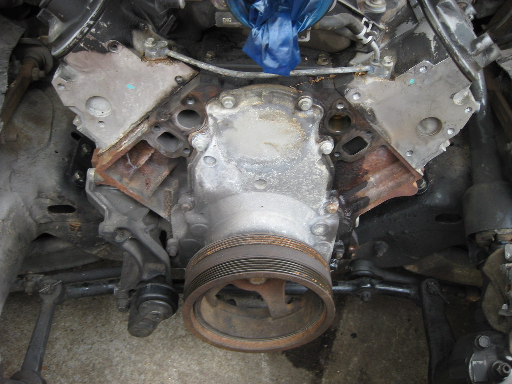
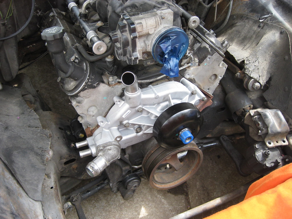
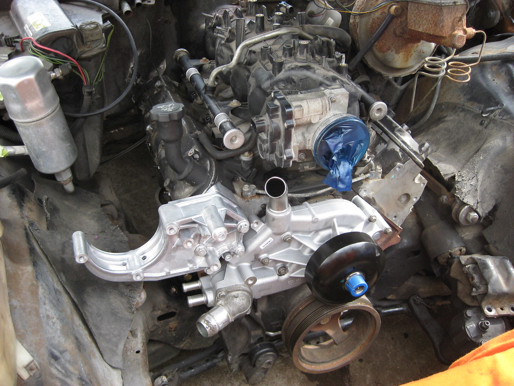
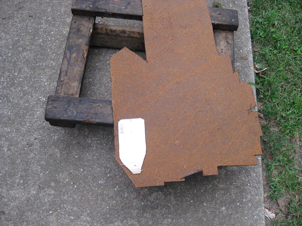
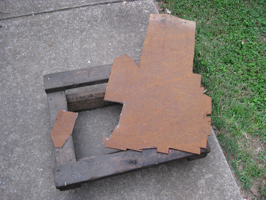
I have spent so much time researching my options for how to make a compressor fit on this car it's maddening. There are different types of compressors and different places to mount those compressors depending on what type they are. The best option would to be to get an entire accessory mounting kit to change all the accessories to better locations, but unfortunately those are very expensive and this project has already fast approached its budget. If I move the engine forward the power steering pump will hit the steering box. If I keep the compressor down low it will interfere with the crossmember. There isn't much room to cut and re-weld a relief in the crossmember because of the location of the engine mounts. The compressor is set back further than the rest of the accessories and runs on its own belt. There are kits to move it forward and have it run on the same belt as all of the other accessories, but even this will now allow it enough room to clear the crossmember. The company Sanden makes a mini-compressor that could possibly fit down low in the forward position, but it is my opinion that this will not give me the cooling capacity I would want for this car. Also, the location is so tight that I woudln't know for sure that it would fit until I ordered a kit and tried to install it. There are kits to move the compressor up, to the topside of the passenger side, and although this is an expensive option, and also creates a more cluttered engine compartment, after much consideration this is the route I chose to go with due to elimination of all other options. Unfortunately, no company that I have been able to find makes a kit to relocate the original compressor at all.
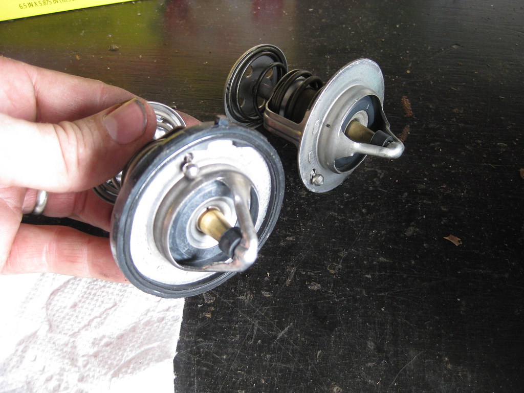
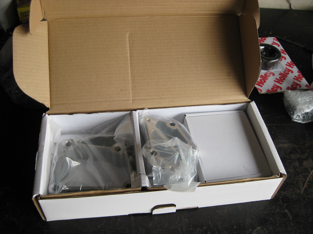
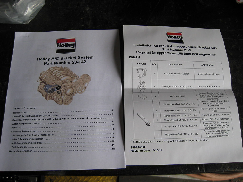
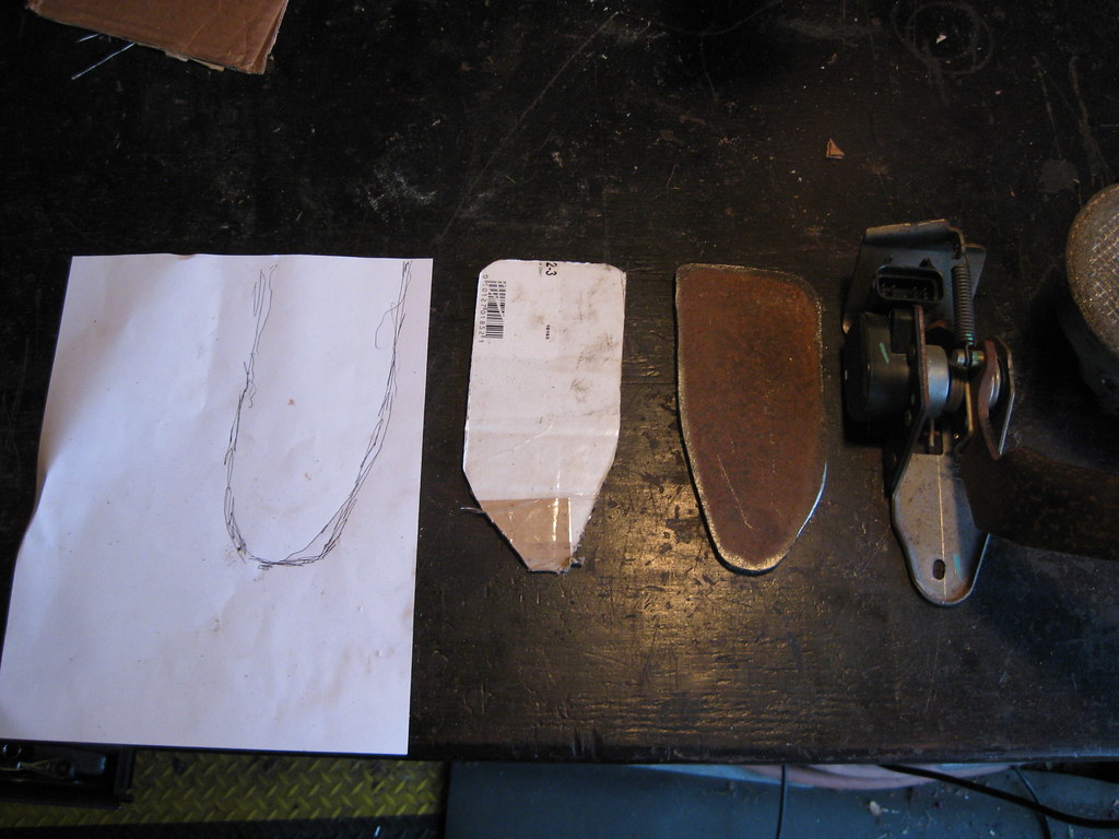
Holley offers two kits that mount a Sanden compressor up top. The kits include all the hardware, brackets, pulleys and idlers necessary for the installation. One kit includes a Sanden 508 compressor and the other kit includes the Sanden SD7 compressor. This is where the problem comes in. I ordered the Holley SD7 kit from an online company, Summit Racing. When it arrived, I found that they had included a SD7 mini-compressor. Sanden produced two compressors that I am interested in for my application, a 508 and a SD7. Within each kind, there are 3 types. The SD7 has two regular sized versions and also makes a SD7-B10, which is a mini-compressor which is physically smaller and has reduced cooling capacity. Some have indicated anecdotal evidence that this smaller compressor has adequate cooling capacity in automobiles comparable or even larger than mine, however after reading the statistics for the output of each model given by Sanden I have concluded that I do not want to go with a mini-compressor. To my knowledge, there is no notation on the website I ordered the kit from that indicates the SD7 would be a mini-compressor rather than a full size. To further complicate things, I looked up the specifications of the kit I ordered and the kit which comes with the Sanden 508, a full sized compressor, and found that both kits come with exactly the same part numbers for the brackets and pulleys, meaning the only difference in the kits is the compressor. I looked into the details for the part number of the bracket that comes in the kit and found that it fits both the Sanden SD7 and the 508. Since my kit came with a SD7-B10 (mini) and the same kit will fit a 508 (full size), it seems to reason that the same brackets would fit the SD7 full size models. Rather than return the entire kit, which is quite large, I called Holley, and waited on hold for a while, to see if they would exchange the compressor. They said I would have to call Summit, the company which I purchased the product through. I called Summit, and waited on hold for a while, and understandably they are not familiar with the intricacies of what is included in each Holley kit because Summit sells thousands of parts from many different vendors. I explained the situation and they ended up calling Holley tech support. At this point the Summit support tech is acting as proxy between Holley and I because the tech refused to talk to both of us on a conference call. Holley denied there was any difference in size between the SD7 and 508. I had the SD7 they sent me on the table next to a 508 and there was, no doubt, a difference. I explained this to the lady on the phone at Summit and she ended up calling Holley tech 3 times. Each time, I had to hold for a lengthy amount of time. Each time, they assured her there was no difference between a SD7 and a 508, and refused to acknowledge that a SD7 "mini" existed. The lady at Summit, who was very understanding and helpful, finally told me I would have to call Holley. I called Holley, again, and waited on hold for almost an hour. When I finally spoke with the tech, they again told me there was no difference in compressors. I explained that there was, that I was physically looking at both and also provided the measurements given on the Sanden website as well as a vintage air website which specifically gave the difference in measurements between the SD7-B10 (mini) and a 508. Finally, the tech agreed there was a difference between the SD7 and 508, but said that all SD7s are the same size. I explained that there are 3 types of SD7s (2 regular sized and one mini) and the one included in the kit was a mini, and that since my kit fits a 508 (regular size) or a SD7, I naturally concluded it must be a regular sized SD7 that the kit was supposed to include, because again the website did not distinguish. The tech then told me that they simply order an SD7 from Sanden and there is no distinguishing as to what size it is. The tech explained they did not distinguish in their description on the kit because they do not offer anything other than the mini, so it is not listed as a description. This is not my first experience with customer service and I realize that a person
must maintain an impartial and non-confrontational attitude when dealing with this issues or the results will become less than favorable. This situation was very frustrating and Holley has an issue with a lack of understanding of the product which they are selling. Unfortunately, there was little to no interesting in resolving this issue. My next step will be to call Summit and ask for the SD7 mini to be swapped out for a 508. Fortunately I made sure to get the direct line to the Summit tech so that when I call back I don't have to re-explain all of this information to a new person. I preferred to have a SD7 full size, however I believe the 508 will be an adequate substitution. Had I known the kit I ordered came with a mini, or had it been in the description of the kit when I ordered it I could have avoided this very frustrating and time consuming situation entirely.
I was supposed to go down to a local exhaust shop on Saturday and borrow some F-body manifolds to make sure they will fit before I try to buy some, but unfortunately I was preoccupied listening to the on-hold music from Holley all morning until the exhaust shop closed, so I didn't make it. While I was on hold, I rewired the fuel pump, which is another frustrating experience with a after-market LS swap manufacturer. I would say dealing with vendors, their products and their instructions has, without a doubt, been the most frustrating and difficult part of this process so far.
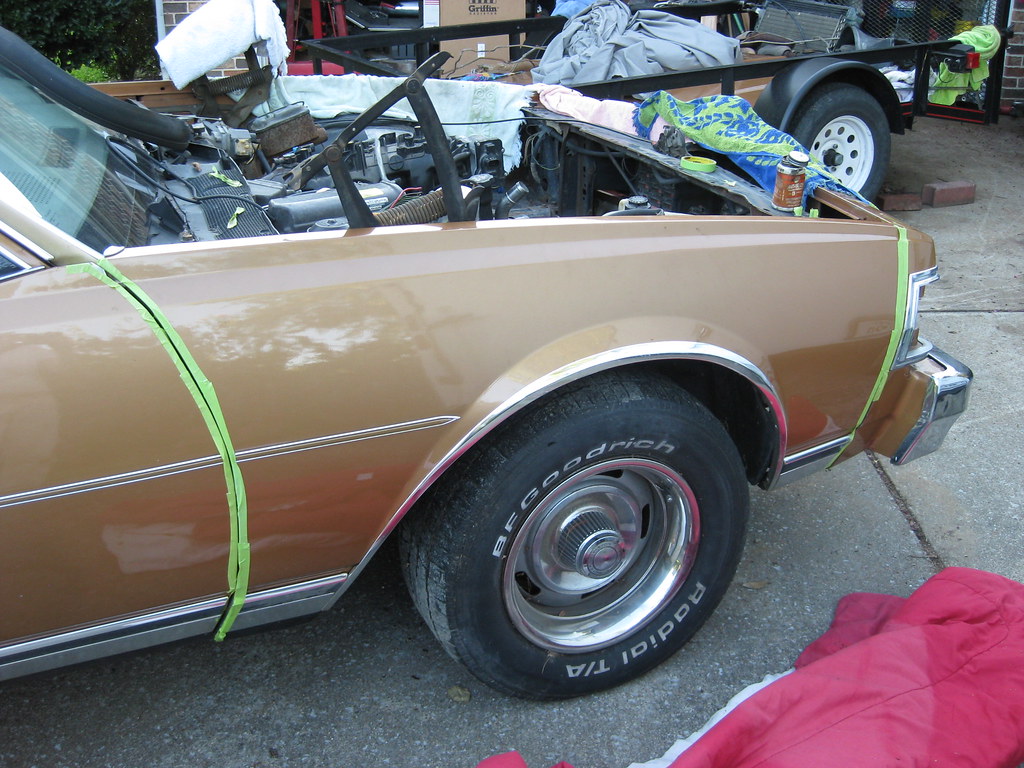
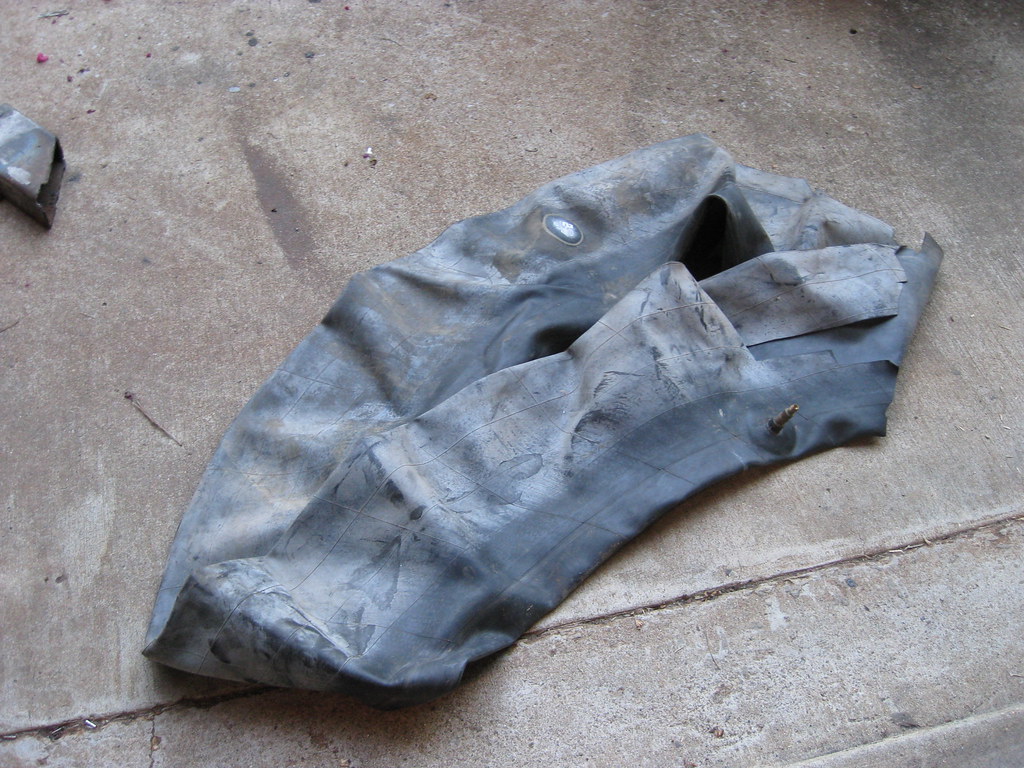
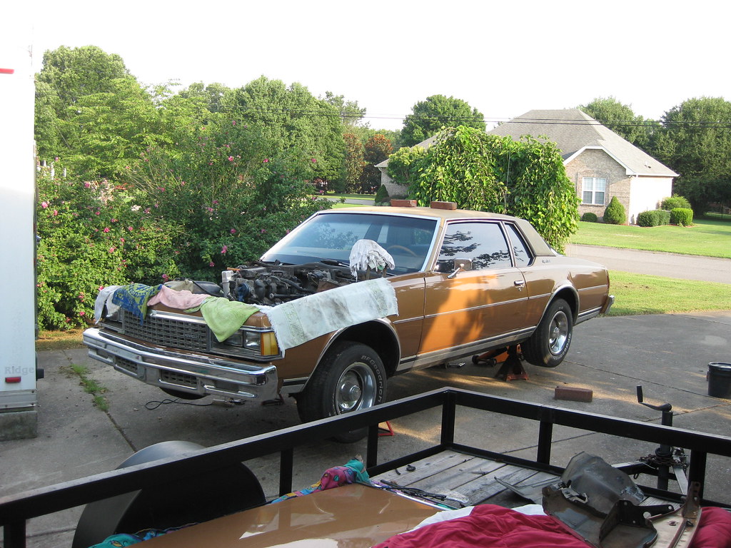
The car goes back into the air. I hope to one day have a shop. I spend a lot of my limited time just getting the car and tools pulled out and put up each time I have a chance to work on the project.
The company I ordered the fuel pump from also makes a harness upgrade for the wiring harness that is in the fuel tank going from the pump to the bottom of the lid on the fuel sending unit assembly. The harness they make is not updated to work with the new-style fuel sending unit assemblies which are now made, but rather are made to fit the stock, original style fuel sending unit assemblies, which, to my knowledge, are no longer made and have been updated. This gas tank is from a 1994 Caprice and the in-tank harnesses were a known issue due to poor design, hence the need for an updated harness.
The company does not provide instructions and requires each buyer to join an online forum to get instructions. When I received approval to join this forum I found that the techs giving the advice did not realize that their harnesses no longer work. I found a different helpful individual on a website devoted to B-bodies that had figured out much of this problem and he helped me a lot, however the company's harness had also been re-designed since he had worked on the problem, however the redesign did not help the harness fit with the new sending units. After several attempts at answers from the company's forum tech, which proved to be insufficient or outright wrong, I realized I would be better off to figure this out myself with the help of the individual from the B-Body forum. Here is part of what I did. I won't know if this solution works until I try to start the car.
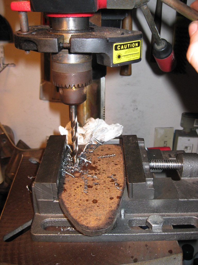
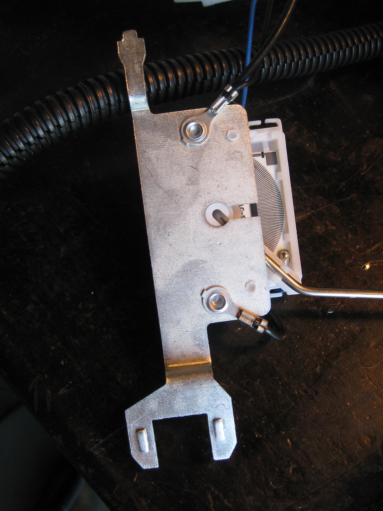
I had to remove the sender from the sending unit assembly. On the newer style units, the wires to the sender are riveted or soldered.
I had to drill out the top rivet and replace it with a screw and jam-nut to hold some of the new wires I would be adding. The wire for the sender provided by the company's kit was not long enough to reach the soldered location on the sender so I had to remove the connector from the original sending unit wire (blue wire) and replace the new harness' wire with the original one.
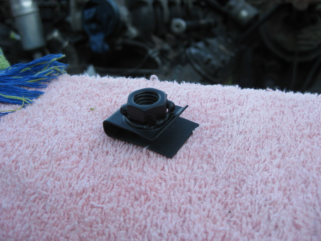
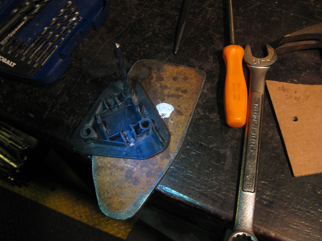
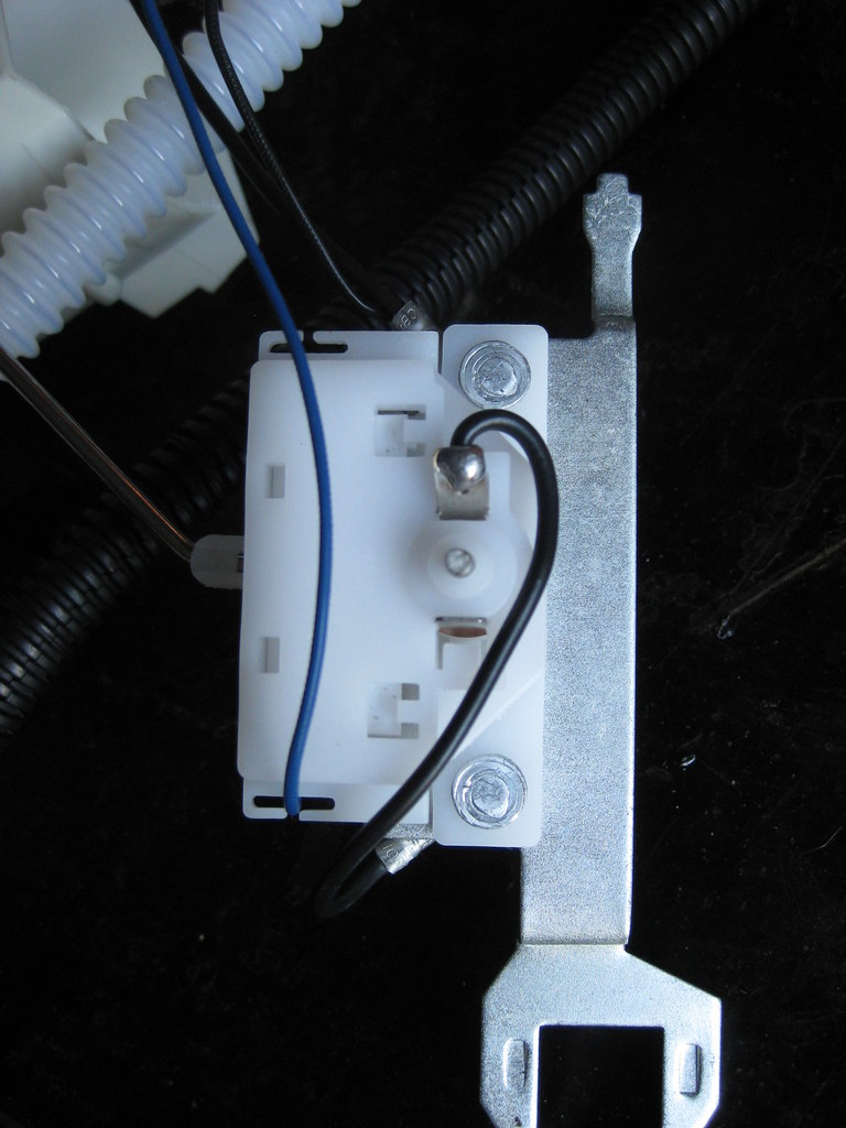
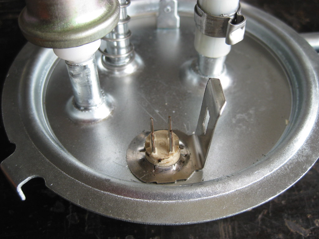
Part of the kit includes removing this connector and clamp from the sending unit assembly lid. I found removing this part to be fairly difficult.
The new piece has 4 pins instead of 3.
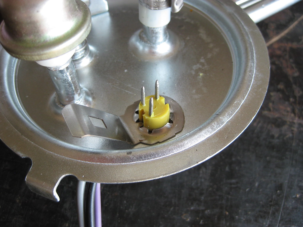
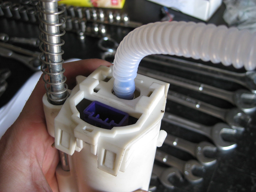
The fuel pump (purple) sits inside a case. I had to use a file to open up the hole so the new plastic hose could fit through.
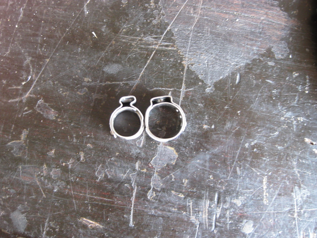
I had to use these clamps to secure the plastic hose. I did not have experience with these clamps and it took a little while to figure out exactly how I was supposed to utilize them properly. Again, proper instructions would have been very helpful.
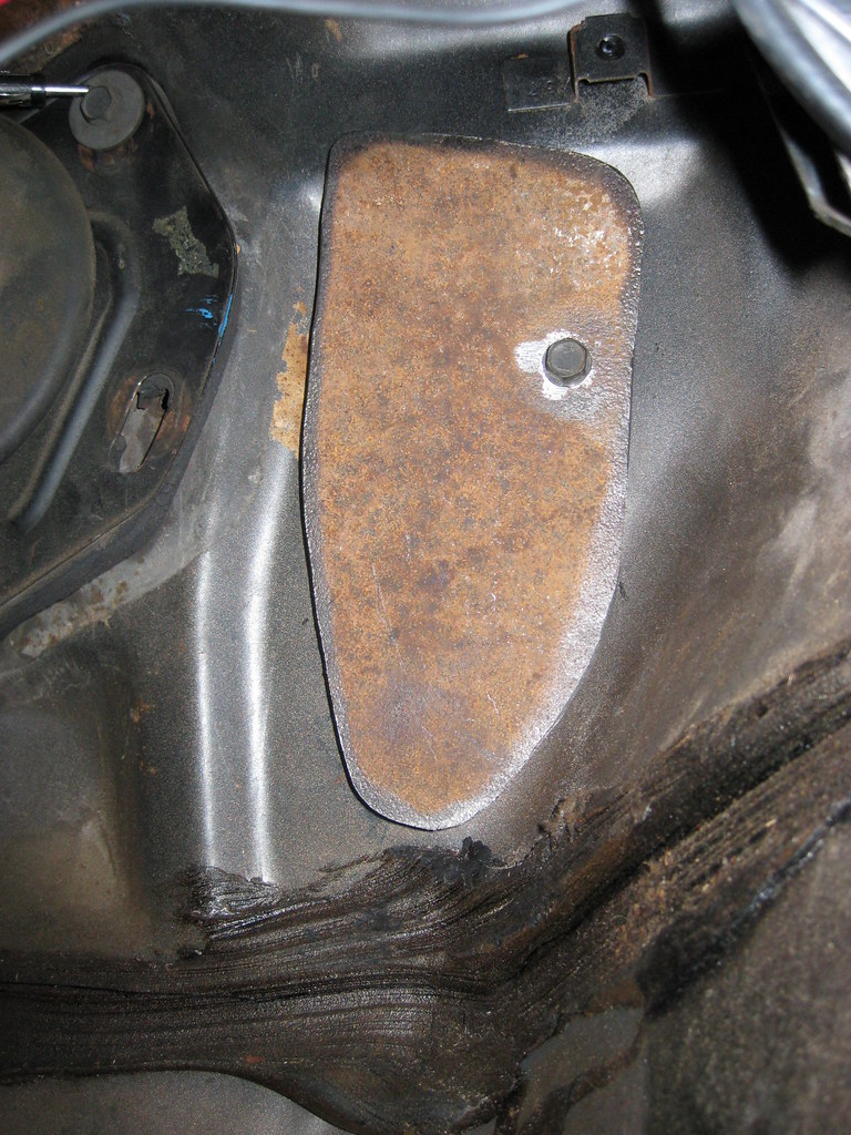
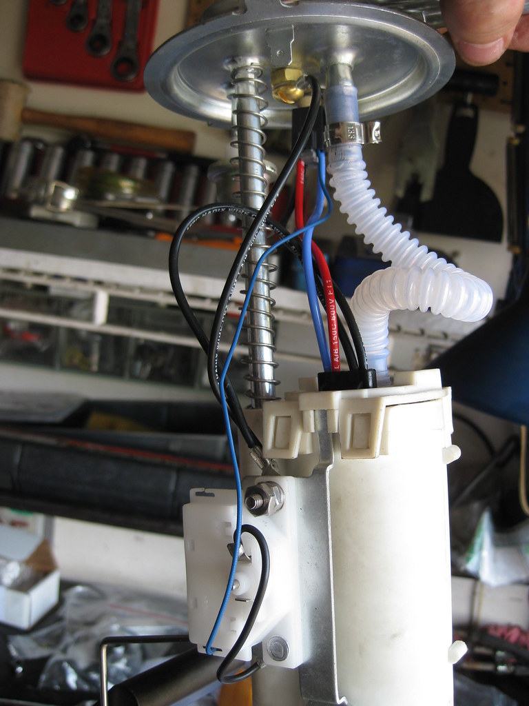
This is how I ended up wiring the final product. A 1/4 hole must be drilled in the lid so a brass stud can be installed which acts as an extra ground.
I then installed the assembly in the '94 Caprice gas tank. Fortunately, Dad happened to stop by and was there when I installed the unit and noticed I had installed it backwards in the tank. You would think I would have noticed when all the metal lines were pointed the wrong direction.
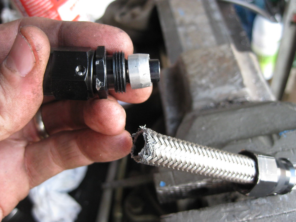
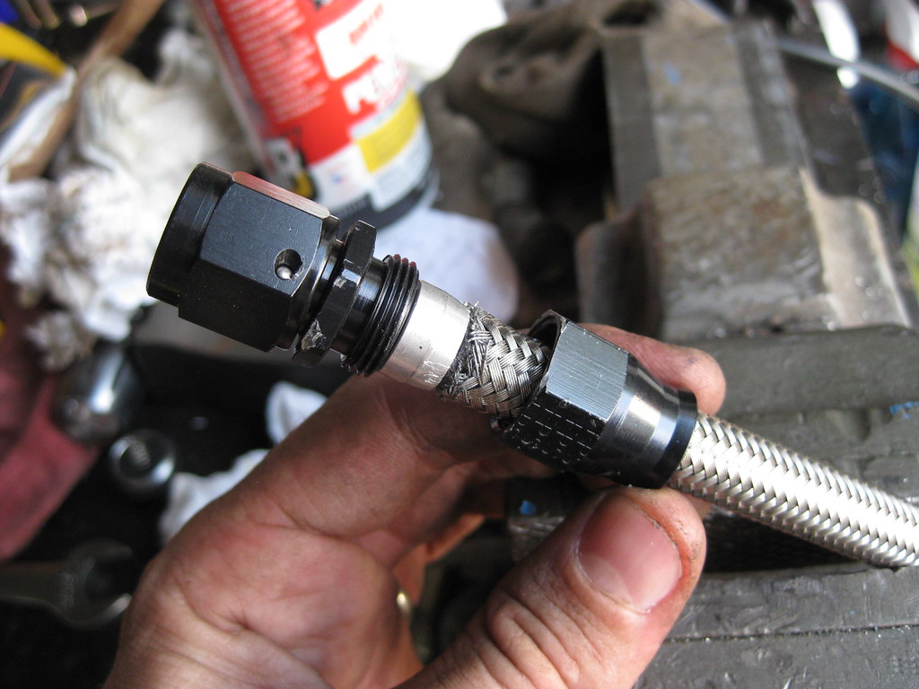
One thing that takes so long with projects like this is learning simple things you just didn't know and have no experience with. At first I was unable to get the AN fittings to clamp and secure the -6 fuel lines properly. After a lot of trial and more and more error I found out that these are not the same type of AN fittings as I have used in the past. These fittings are called PTFE fittings, which means they have the brass ferrule, or "olive" as they are referred to, in the picture below.
I was simply installing the fittings as shown below.
This is incorrect. The proper way to use these fittings is to slide the fitting on the very right of this picture on first, then use a small screwdriver to peel the steel braids back away from the hose inside. The ferrule then slides over the hose but under the steel braid. When the fitting on the right in the picture below is then slid forward and screwed onto the threads it creates a sandwich of the tube from the fitting on the left going into the hose, then the hose, then the ferrule over the hose, then the steel braids over the ferrule and the fitting on the right on top. After I learned this, getting the fittings on the lines was not much trouble at all. Also, the threads of the fitting need to be lubricated. I used air tool lubricant. This step is on all the instructions I saw for these fittings. I forgot to use lubrication on one of the threads and when I got the fitting screwed together I could feel the heat from the friction.
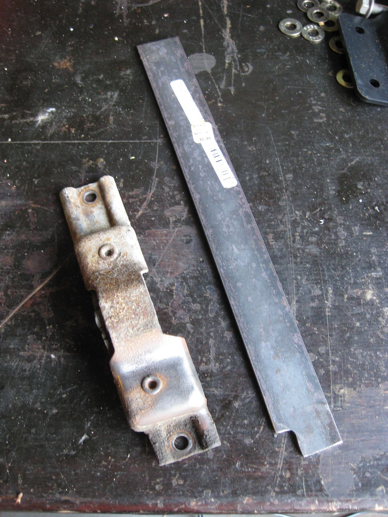
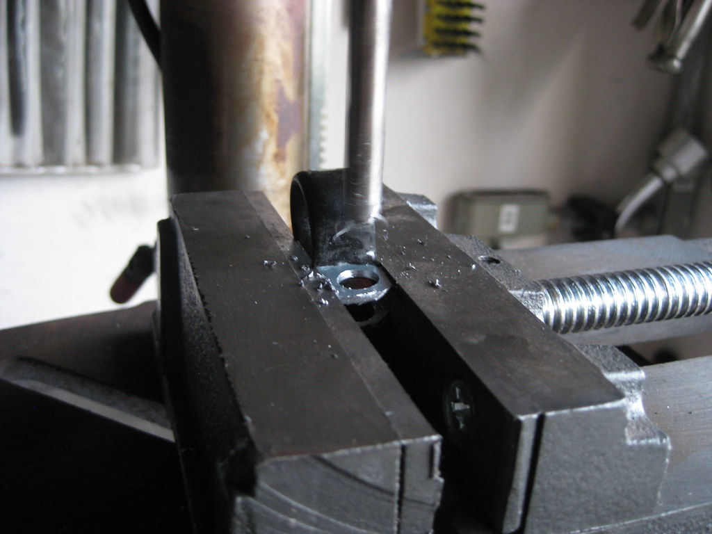
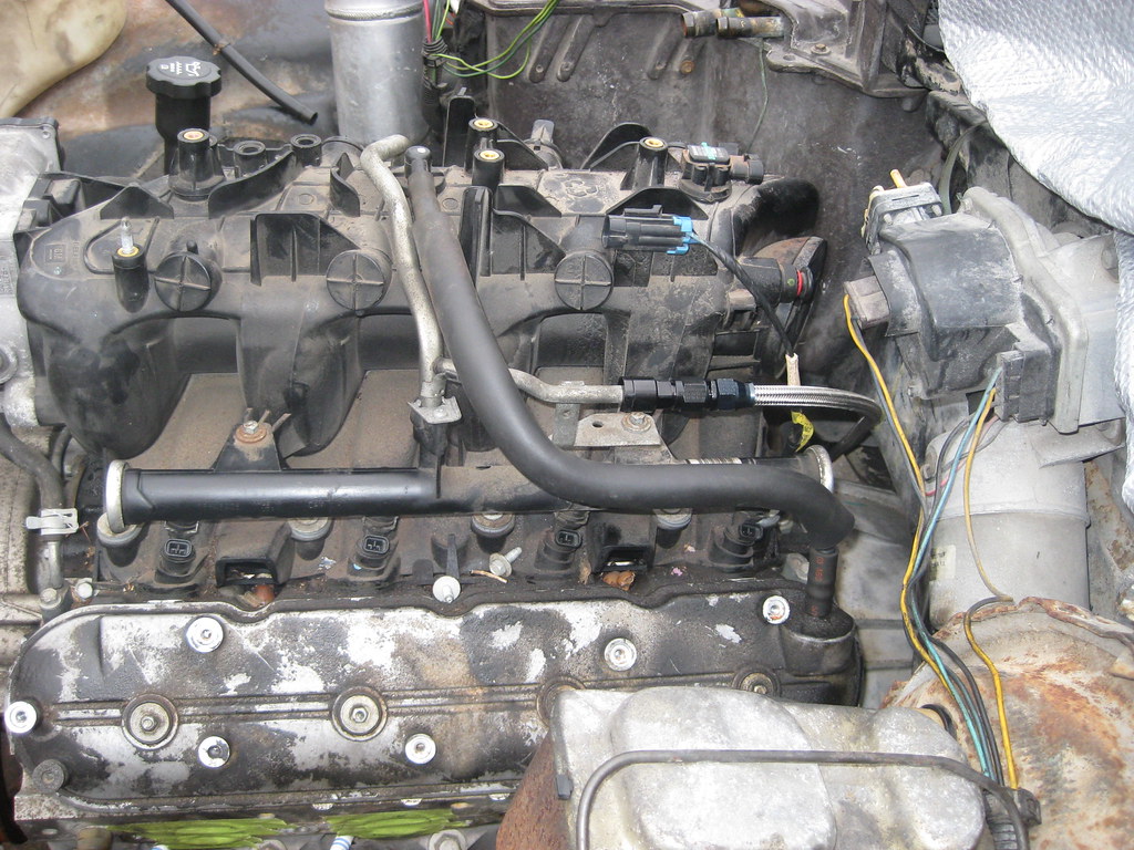
The adel clamps I ordered to secure the fuel lines would not fit with the original bolts that held the old fuel line clamps. I had to drill out the holes in each clamp and also trim down part of the flanges on each one of them.
The fuel rail only has one line because this 2004 5.3 LY7 is a returnless style fuel rail.
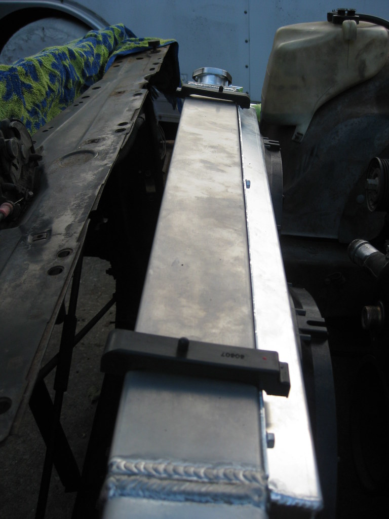
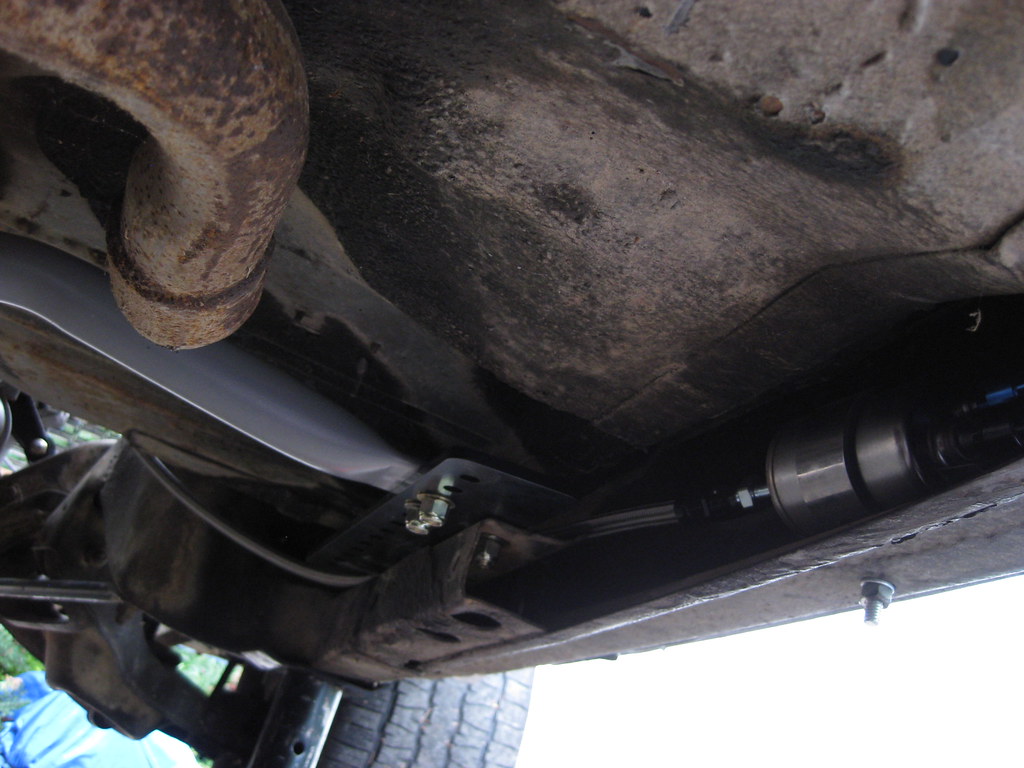
The line runs down the passenger side and over the frame rail to the filter/regulator, which I mounted mid-way on top of the framerail. I have not yet installed all of the clamps to secure the fuel line. I almost mounted the regulator in the very back of the car over the axle, and I saw where many people have done this, but I decided to move it forward, mid-way on the car. I don't have any evidence to support this but I feel as though this would give the regulator an easier time of managing the PSI in the shorter line running to the fuel rail than if I had mounted the regulator in the back of the car. The stock locations for these regulators seem to be about mid-way on the car as well, but this could also be a space requirement more than a design choice. Also, the pump I purchased was for an LT1 and is slightly under the 58 psi of what a LS motor requires. I have heard that others have used this setup with no problem, but I suspect that relieving any extra load on the regulator would be helpful.
The line continues down the frame rail, using a stock location from the old fuel line for the new adel clamps.
Another reused stock clamp location using new adel clamps. These clamps seem to be a bit oversized for the -6 lines and I may end up replacing them with clamps that will hold the lines a bit tighter.
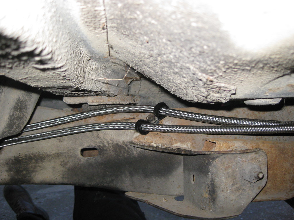
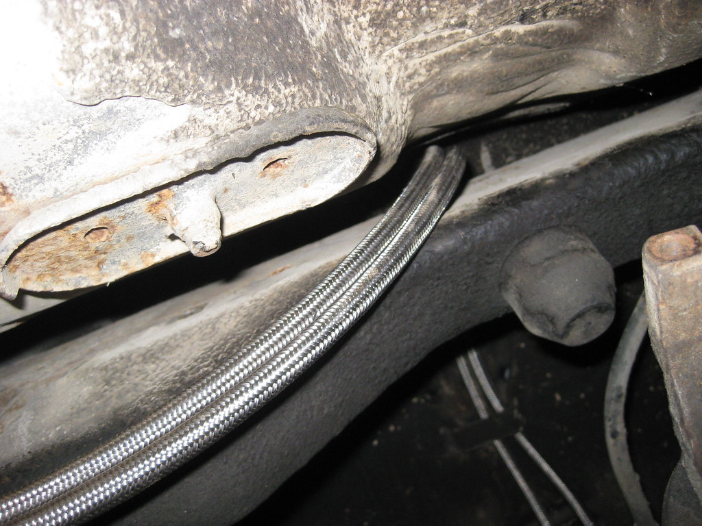
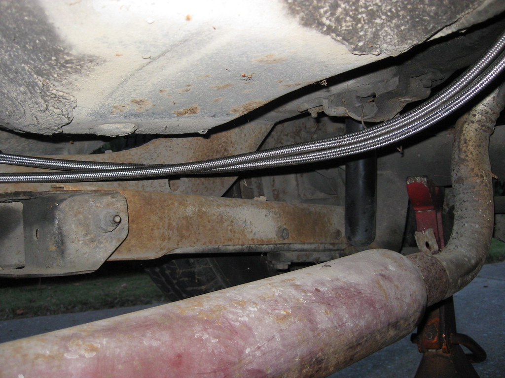
The line continues over the frame in the rear, which is over the top of the rear axle. I will add more clamps soon.
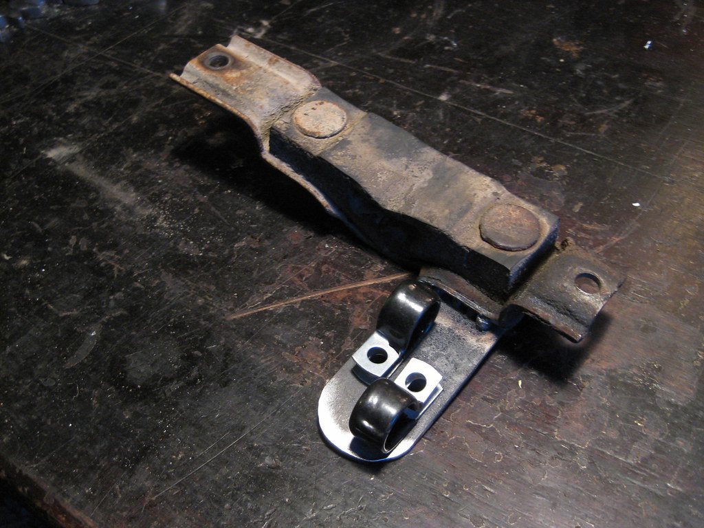
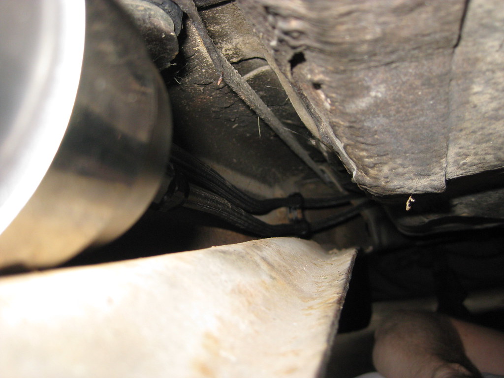
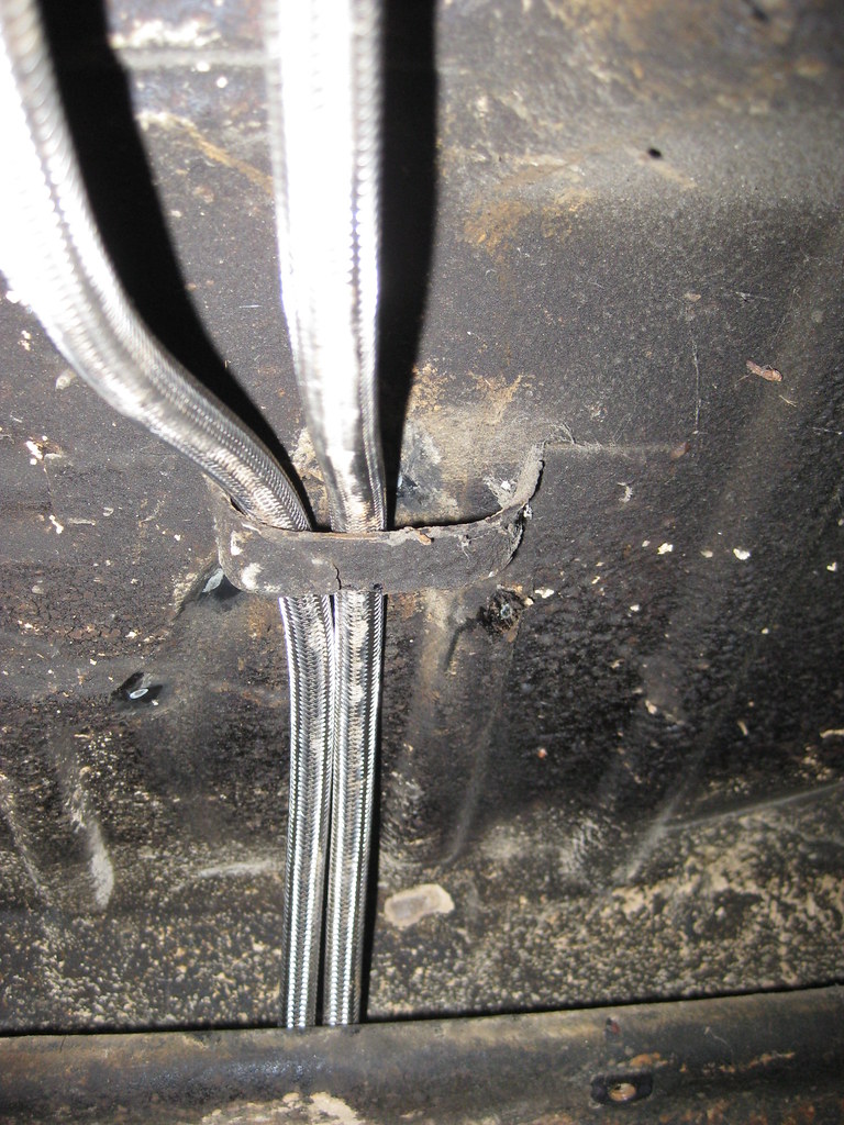
After going over the axle the lines go through the original fuel hose bracket.
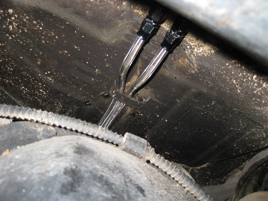
They finally terminate at the tank. I have not yet installed the fuel tank vent tube.
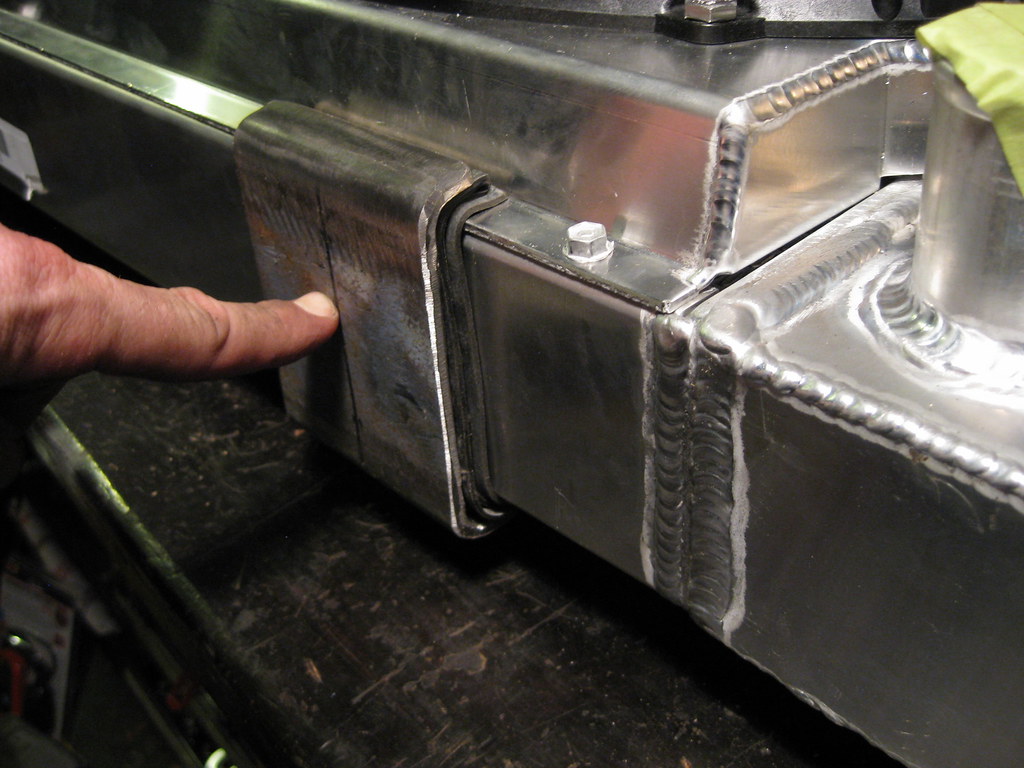
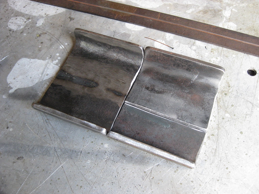
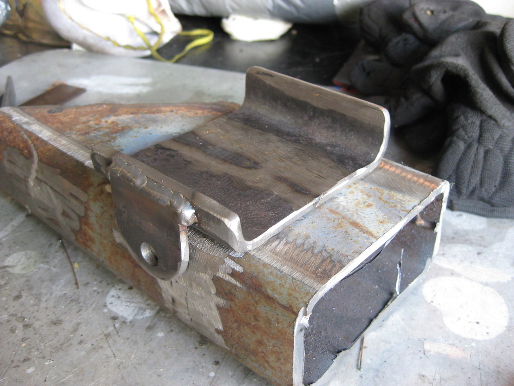
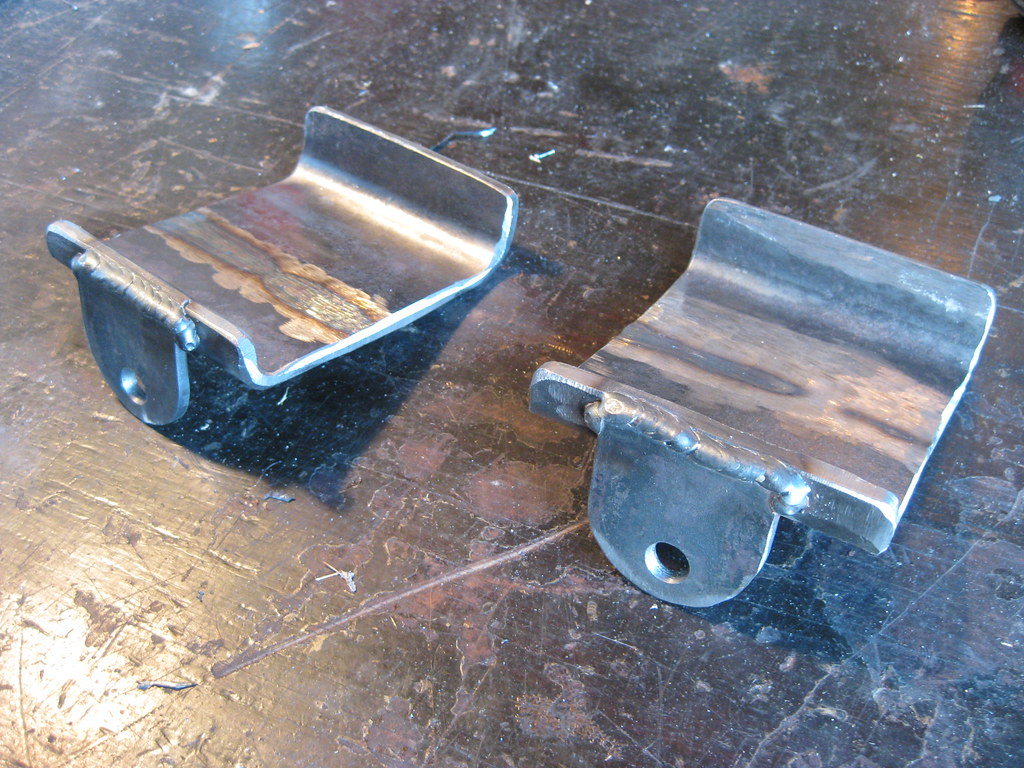
If you look right above the lines here you'll see the old exhaust hanger mount. I no longer use this mount because of the dual exhaust. I've removed this mount and I am going to weld a mounting tab to the bottom to provide a mounting location for two more adel clamps.