It has been quite a while since I have been able to post any updates on my progress. Most of the things I have been working on aren't things you can take pictures of because the majority of it has been sitting at the computer and making telephone calls trying to weed out fact from fiction concerning the installation of a 700R4 into a vehicle it wasn't meant for. I believe in my last post we had just removed the transmission in the midst of a downpour. A few days after I went to the local Pull-A-Part in search of a yoke to fit the 700R4 transmission that would replace the TH400 we pulled out. After some research I found that the yoke from a 4L60E transmission is the same as the yoke from a 700R4. This made it much easier to find one in the junkyard. Jacob went with me to the yard, but when we got there we found that you must be 16 years old to get inside. He had to wait in the lobby area and as he sat there they coincidentally re-hung a sign, literally right above the chair he was sitting in, that had been down for a while. The sign informed patrons to not leave children unattended. Even the workers there had a laugh about that one. I was going to pick up a few more things while I was there but since Jacob was waiting while I searched the whole yard for a suitable yoke I tried to hurry as much as possible. Also, there was a huge thunderstorm moving in. Since the junkyard is on a hill I was able to see the rain moving in from the nearby mountains.
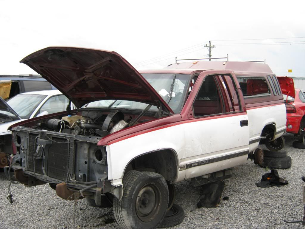
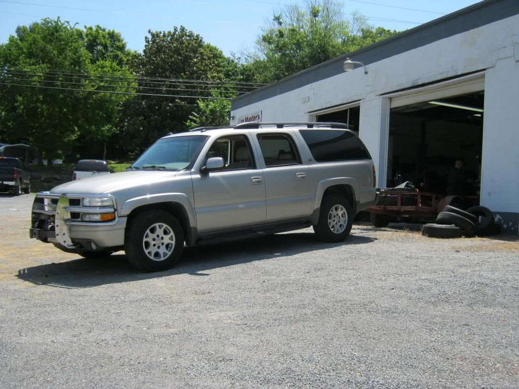
Many of the yokes have been pulled from the transmissions and laid on the ground or in the back of trucks, which causes their bare steel to rust immediately. I found one that was still inside the transmission, which also meant the driveshaft was still attached. The donor vehicle was this 1988 GMC pick-up. There was also a full size van that I considered, but it was a heavy duty and I thought it possibly may have had the 4L80E transmission rather than the 4L60E, which I believed might have had a different yoke and I wasn't willing to take the risk.

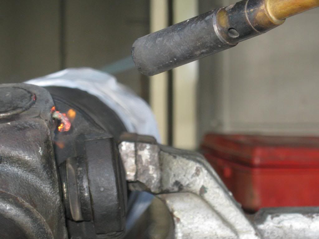
It was very fortunate I had just encountered the GM style, nylon U-Joints with the removal of The Clam's driveshaft because I had just learned with them that heat is necessary for their removal. Had I not learned this I would have beaten on the joint in the yard until I was blue in the face. I also would have gotten wet. Since I had no source of heat at the junkyard and had learned heat was necessary, I had to buy the yoke and driveshaft together since I was not able to separate them. It ended up not costing too much extra because they only charged me for the driveshaft, not noticing the yoke was attached on the end, despite the fact I told them that I only wanted the yoke and that the driveshaft was bent and junk anyway. They said I would have to buy both, yet quickly forgot and when I got home saw I was only charged for the driveshaft. I took it to the scrapyard after I removed it from the yoke and got a handsome $2.00 for it. As Jacob and I wrapped the driveshaft in paper towels to keep from getting the inside of dad's Suburban greasey the storm hit and we literally made it inside the Suburban right as the bottom let loose. Once home, I heated the nylon until it popped out of the U-Joint like a snake.

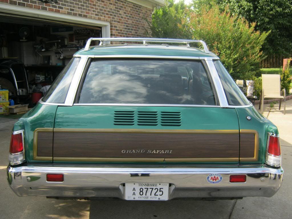
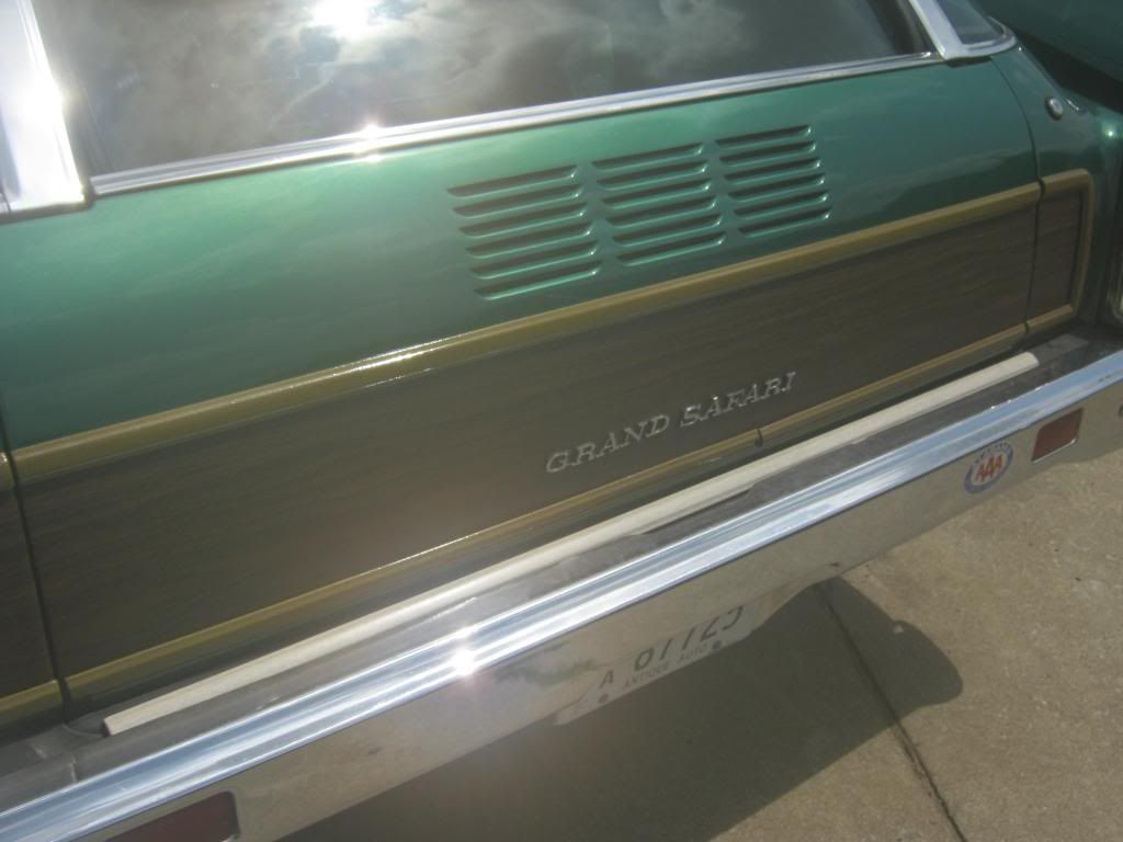
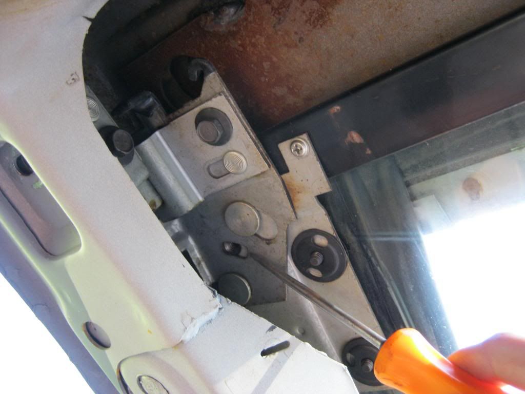
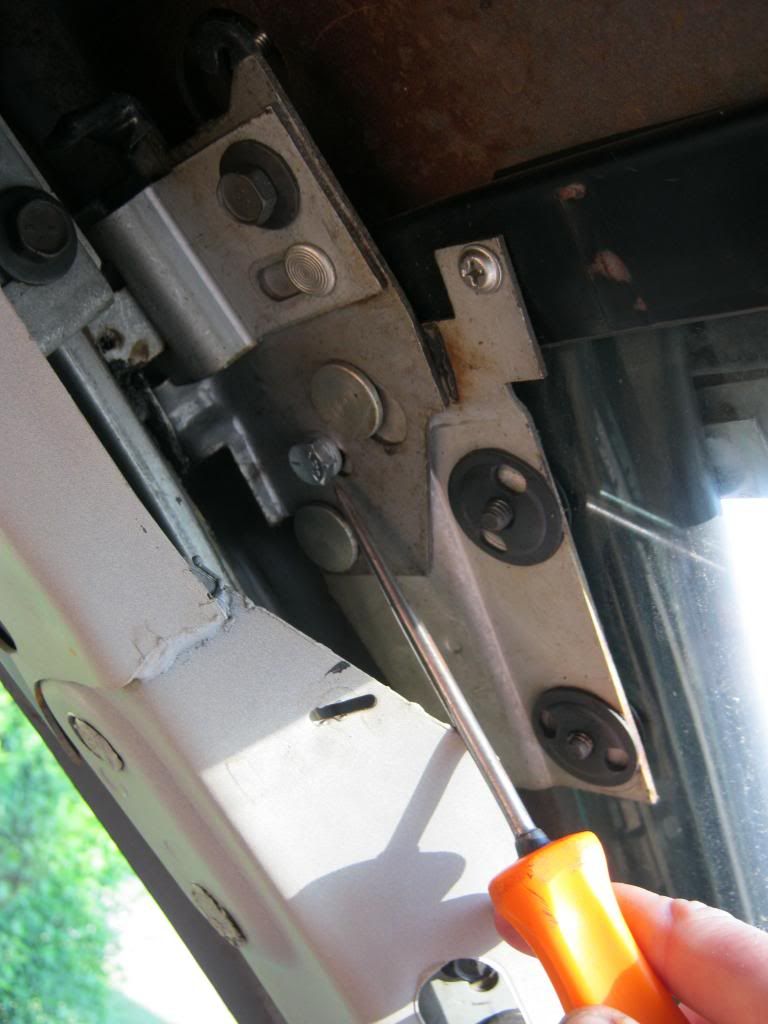
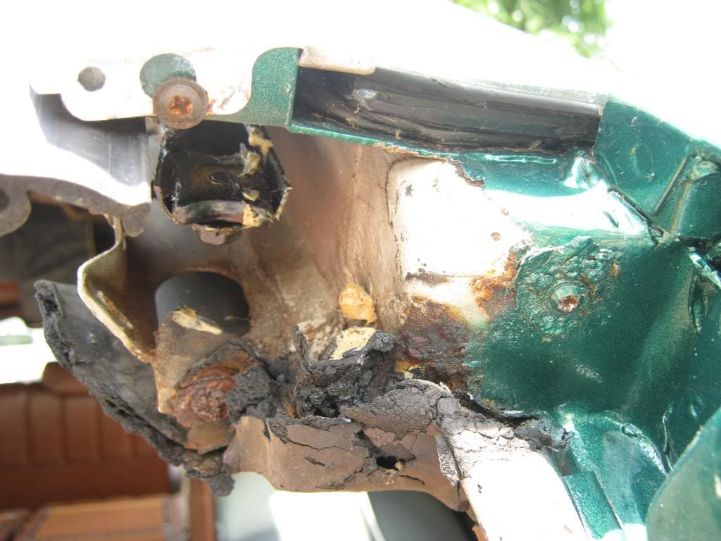
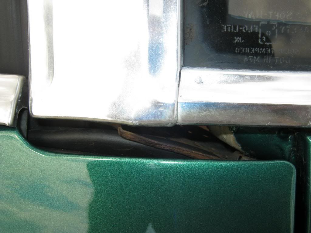
This is the upper, passenger side corner, where the tailgate raises up against the body. There is a screw on the right that gave me much grief to remove. Also, if you look directly below the visible screw on the left you will see a rusty area. This rusty area is the second screw which gave me a lot of trouble to remove. I had to do this in the direct sunlight and it was very, very hot this day, making this a near miserable task. This, and the comparable corner on the other side of the car, are where I will have to come up with a way to seal against water that is entering the car.

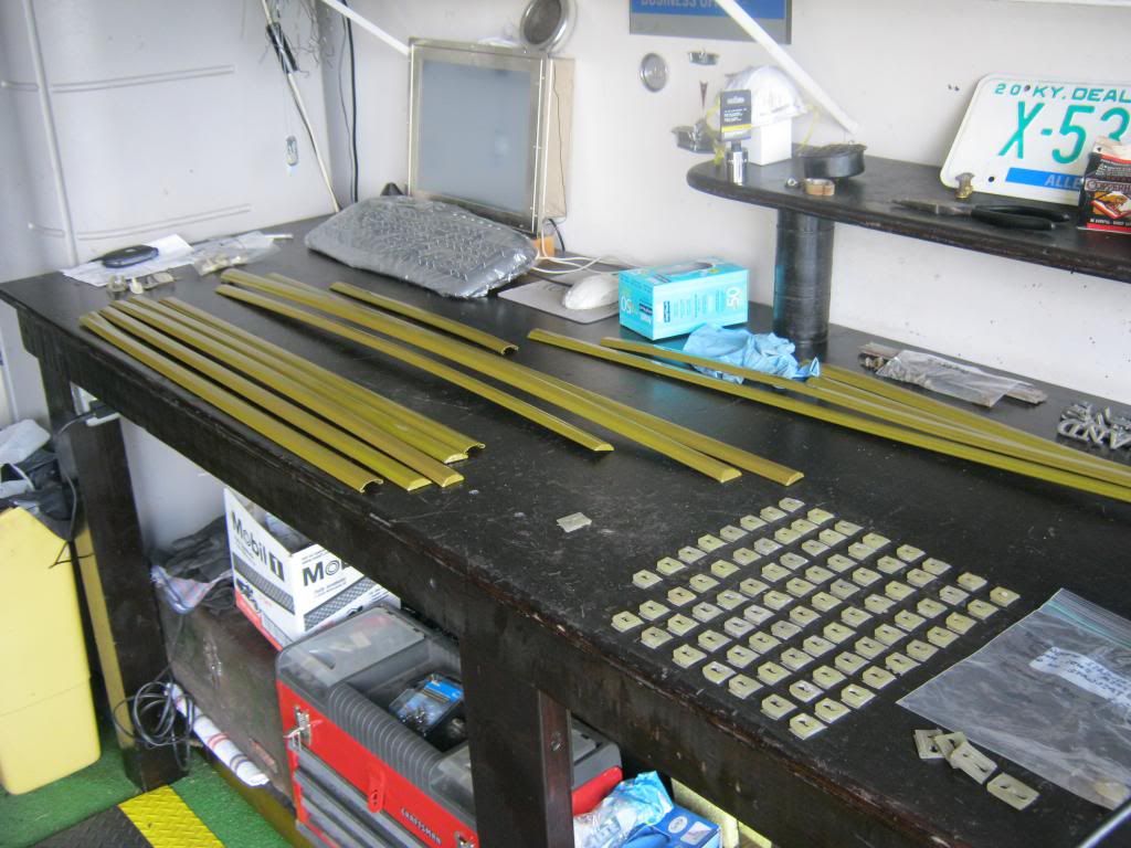
I am a member of a group of station wagon enthusiasts on the internet that have a forum. One of its members sent me this metal piece that screws into the location you see here. I was very thankful because this piece is nearly impossible to find. Mine had rusted beyond use and pieces can actually still be seen stuck behind the screws in the picture above. I will sandblast this piece, repaint it and use it to attach a sealer that will lock out the water in this area.

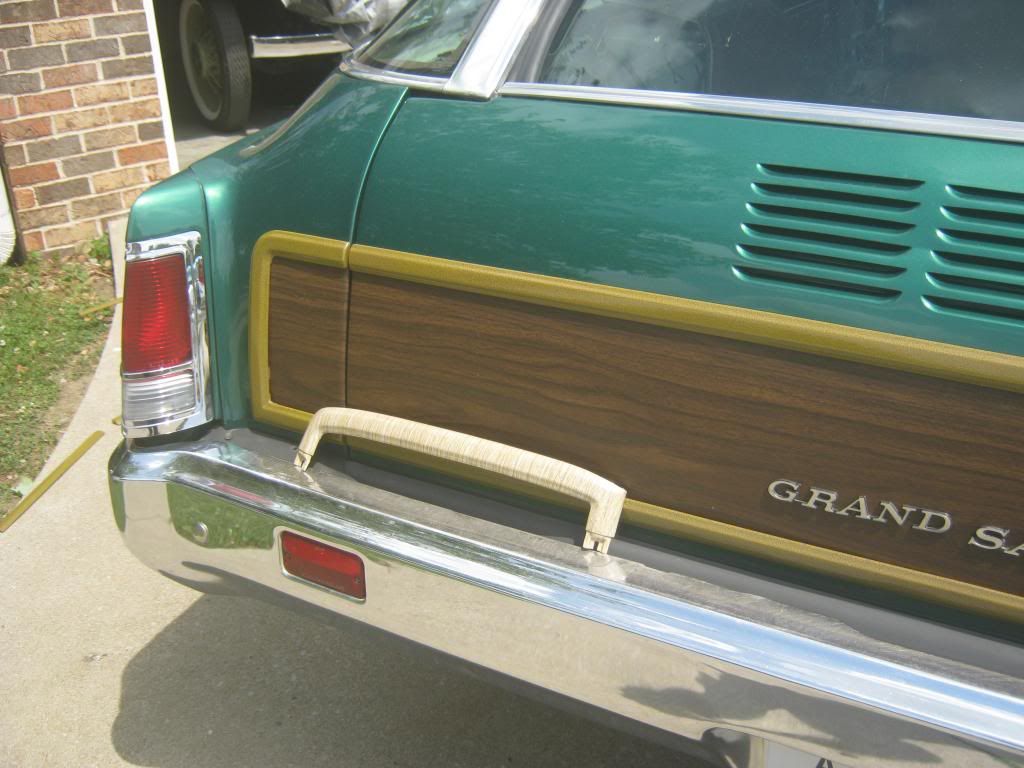
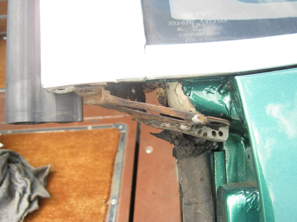
This is the same area with the tailgate closed. You can see the weatherstrip seals against the bottom of the metal piece, but more will be required above it. Also, though not visible in the picture, the big problem is that there are drain holes in this area in the tailgate and the window rubber and the tailgate rubber must be modified and attached in such a way that they will drain the water into the holes. They currently just allow the water to pool up at the base of the window. My window/tailgate switch broke yet again and finally got so bad I had to stop work in this area.
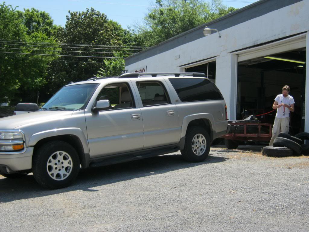
After a lot of searching I finally found a reputable shop in Kentucky, coincidentally in the same town that we used to have the dealership. Dad went with me when I delivered it. A little over a week later, Jacob went with me to pick it up.
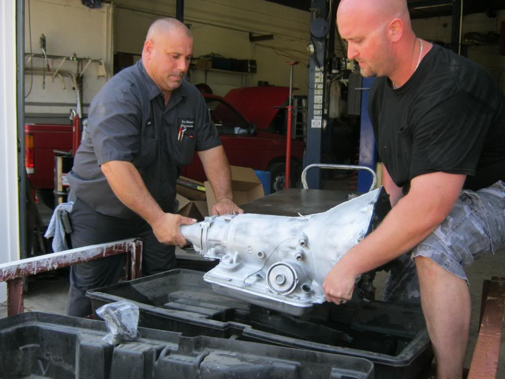
Fortunately there was plenty of help to load it into the transmission case I'd brought on the trailer.


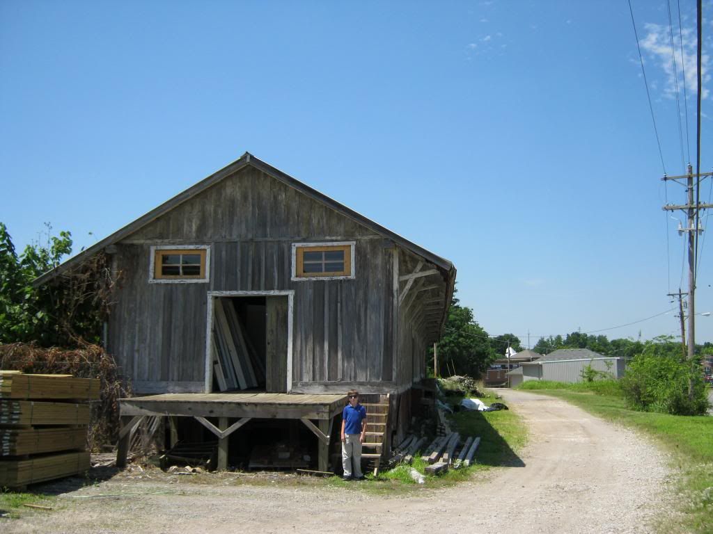
There used to be a dedicated railway that went between our cities and one other. I have done a bit of searching to find information on the history of this railway and parts of it are still able to be found along the way. Jacob and I stopped to see what's left of the old depot, which is now being used as a storage building for a lumber supply store. As we were leaving an older gentleman inquired about what we were looking at and he ended up taking us through the building and telling us a lot of stories. One, for example, was how the liquor shipped in by train used to be stored in what can be seen as the left, front of the building in the picture. When the drunks in the town found out about this they used to drill holes into the floor and through the barrels, draining out all of the liquor. The railway was eventually decommissioned due to the extensive use of wooden trusses, which caused the cost of the upkeep of the railway to be more than the profit it could make.

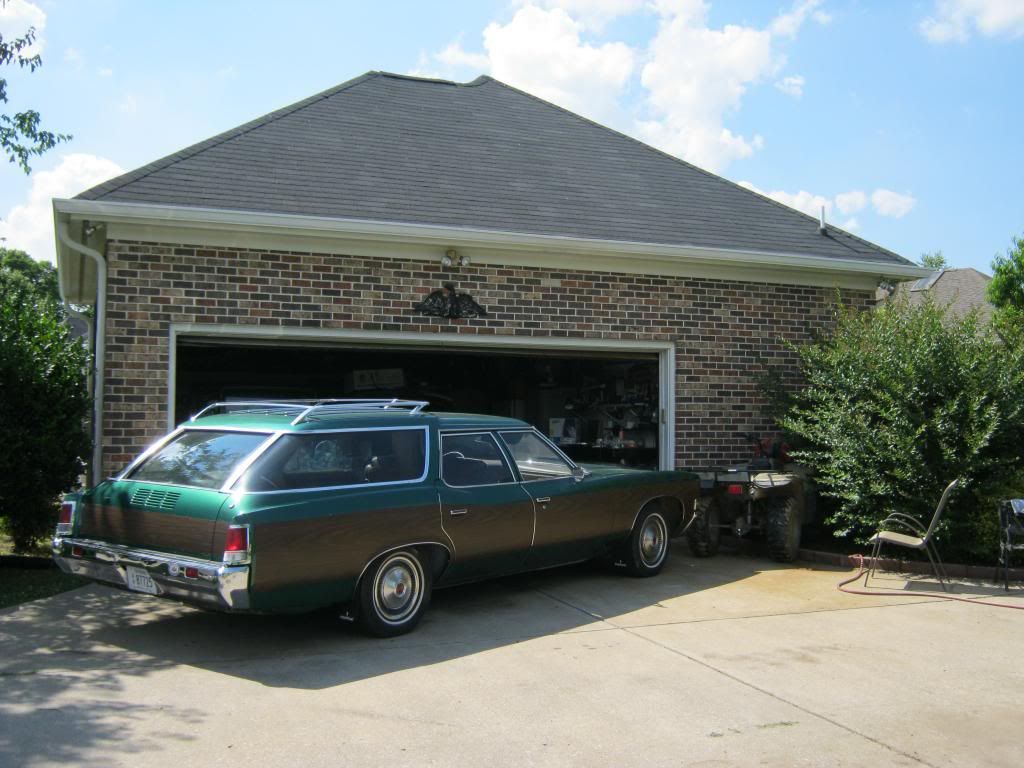
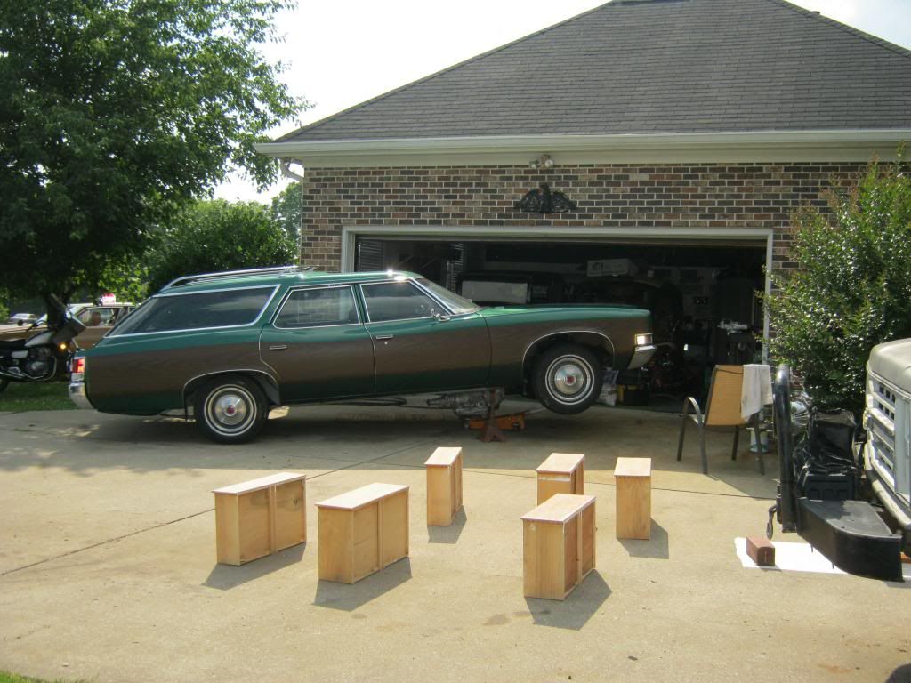
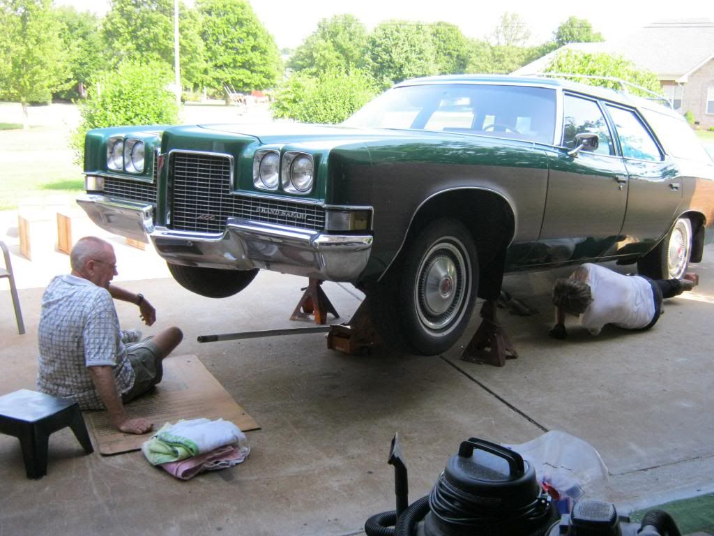
With no transmission, The Clam had been moved over to the side of the driveway. I hauled dad's four wheeler over to my house to pull The Clam back up to the garage, with April (and Rose) at the helm, for the transmission install.
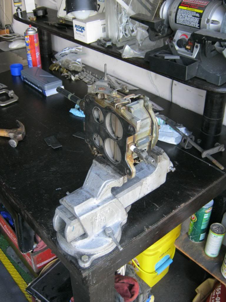
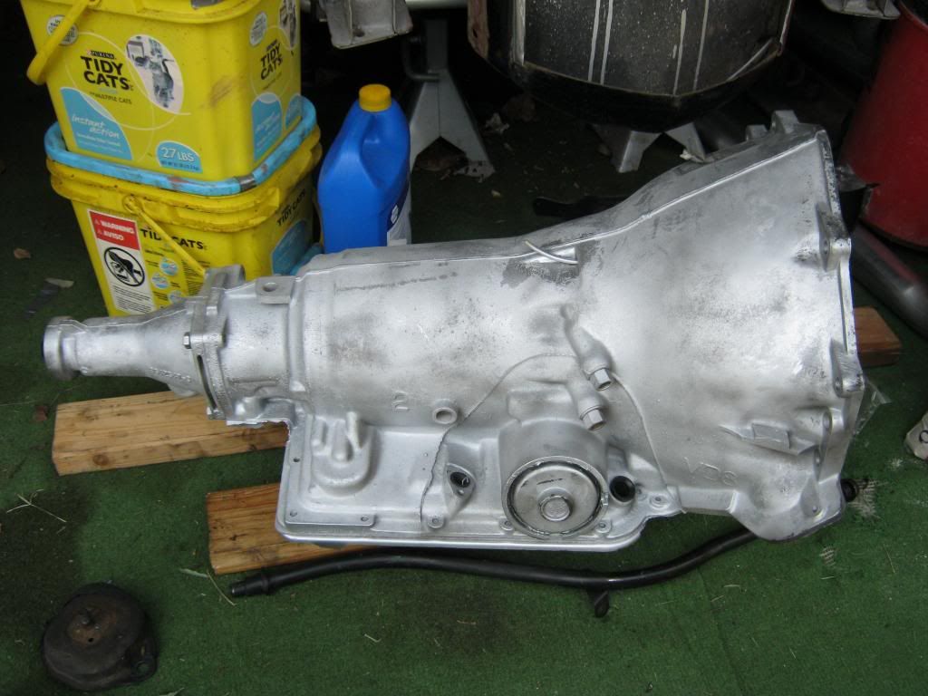
Here is the 700R4 waiting to be installed

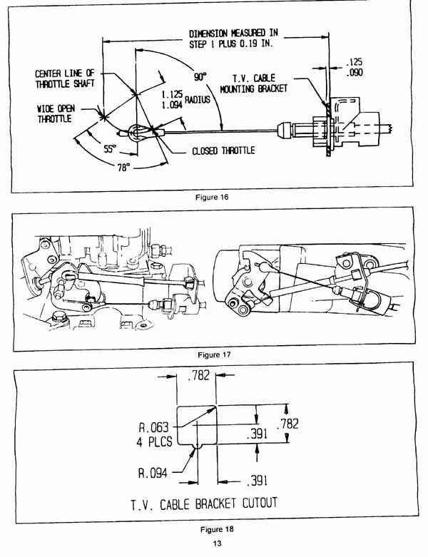
I discovered that the 700R4 transmission is operated by the use of fluid pressure, which is controlled by a TV cable that runs from the transmission to the carburetor. I learned that the setup of this TV cable and its mounting to the carburetor is extremely critical to the life of the transmission. Even small variations of the TV mount's intended setup can cause the transmission to fail. It took many hours of research to learn the truth about how to properly setup these transmissions. I spent almost an entire week sitting up past midnight scouring the internet. There is a vast, vast amount of information and just as many opinions on how to install and setup these transmissions and going from zero knowledge to being able to weed through to the correct information is a timely and frustrating process. I called a company that supposedly specializes in these setups. After talking to me with a sorry attitude and tone, the owner took the information from my carburetor and I sent him pictures. I never heard from him again. He was supposed to determine which of their custom brackets would work and get back to me. I found his attitude to be so poor that I had little desire to contact him further. Also, I found their kits to be very pricey. I finally continued the research myself and determined what parts I would need and the basic idea of how to install them.
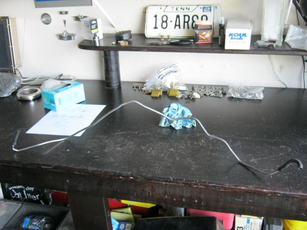
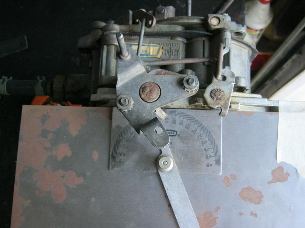
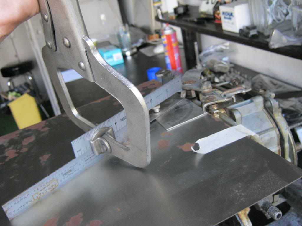
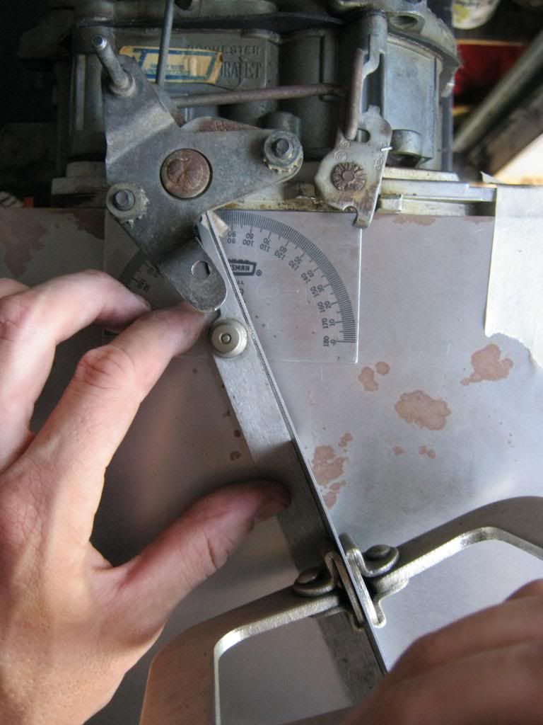
It seems that a throttle cable can simply be installed, but a TV cable must maintain perfect geometry in reference to the throttle arm. If the hole drilled in the throttle arm to mount the TV cable is not exactly the correct angle and distance from the center of the throttle shaft it will cause shifting problems and transmission failure. There are kits which bolt on, however none of these kits fit my specific application. Some people have found that particular years of carburetors that came with specific transmissions can be taken apart and the pieces can be installed in earlier style carburetors. Others have determined the exact measurements of where to drill the new mounting hole. Also, the TV cable must be supported by a mount that attaches either to the manifold or the rear of the carburetor. If you use a factory style TV cable from a vehicle from the 1980s, the spacing between the mounting point on the arm of the carb and the manifold/carburetor mount must match exactly as it did in its original setup. I found that there are aftermarket, universal TV cables which can be adjusted to fit any spacing needed.
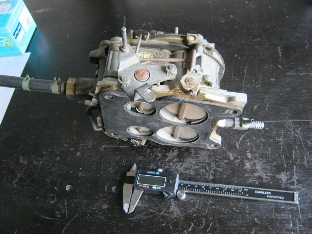
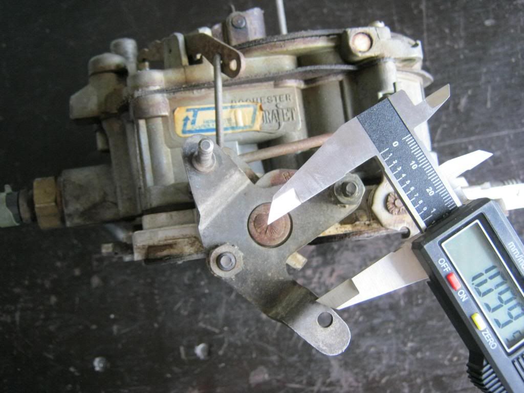
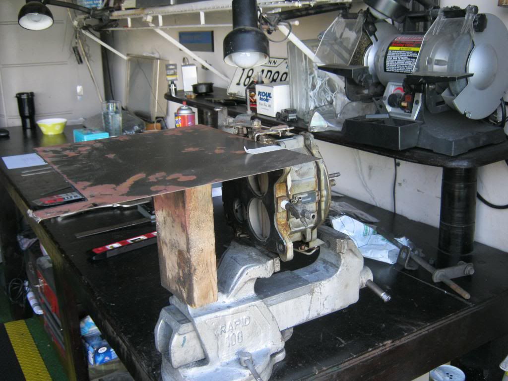
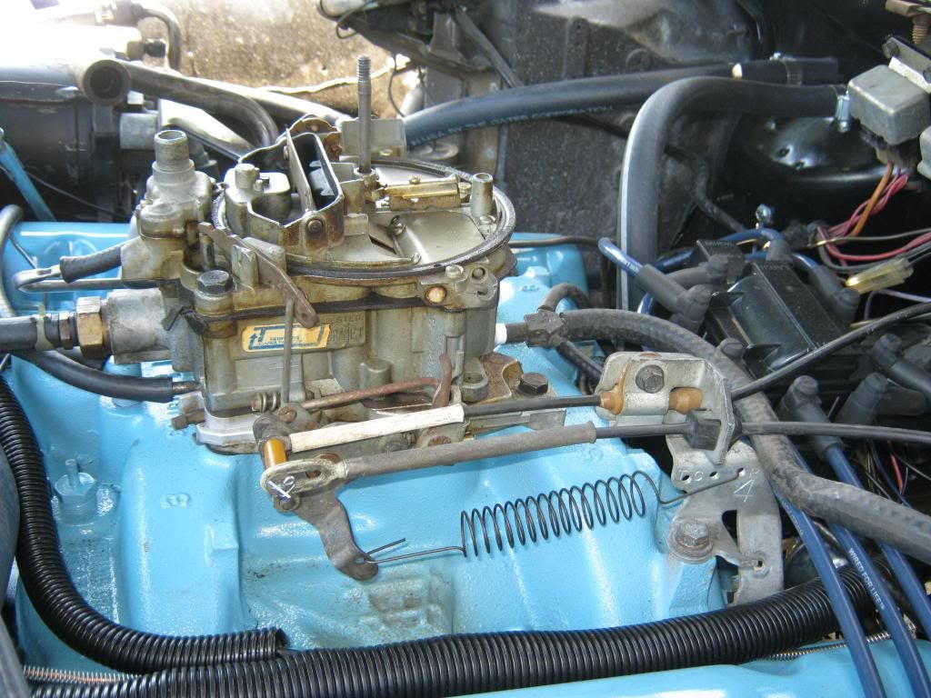
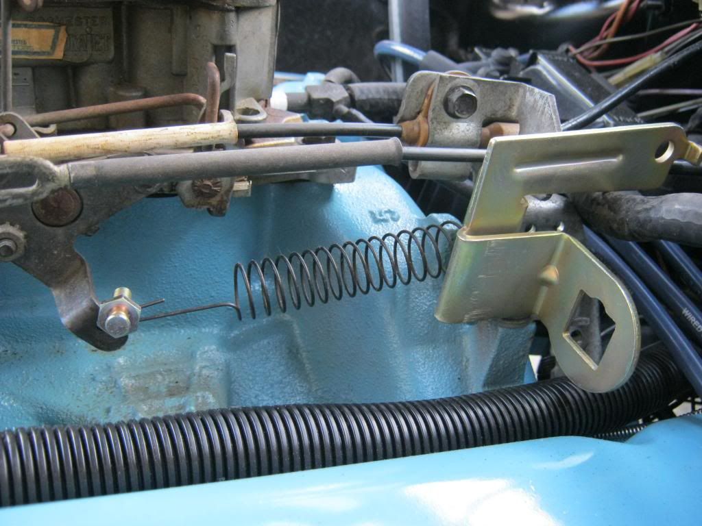
This is my carburetor setup, which makes things a bit confusing because there are a lot of things in the way. The throttle cable, the cruise control cable and the rear mounting brackets leave little room for any of the available mounts.

After a lot of research I pieced together some parts from different kits and stores that had them available. Though far from the final result, this picture gives a good idea of how I will go about achieving the TV cable bracket. The plastic encasement for the TV cable will snap into the mount on the right, which I will have to cut apart and weld back together to fit my needs, and the mounting stud on the left is designed to fit the plastic clip on the end of TV cables and will be mounted on the end of the arm shown here. It may be necessary, after my measurements are complete, to weld extra material onto this arm to allow the stud to be mounted in the exact right location. It is also very important to keep the TV cable mount aligned with where the TV cable stud will be to allow the cable to maintain a straight angle and allow the cable to remain straight through its pull travel as the arm on the carburetor throttle plate swings forward when the gas is pushed. If necessary, the throttle return spring, shown in the picture, can be relocated, as it's placement is not critical.

Another issue I had was how to mount a 700R4, a Chevrolet transmission, to a Pontiac engine, and if it would fit. After what seemed like endless hours of research to determine if I should use a 700R4 or a 200-4R transmission, I decided to go with a 700R4. One downside to this was that a 200-4R transmission has a dual bolt pattern, which means it can bolt to a Chevrolet engine or it can bolt to the other set of GM engines that share their own bolt pattern, the Buick, Oldsmobile or Pontiac engines, which I found are commonly referred to as BOP engines. I then had to delve further into learning about the operation of the 700R4 transmission to determine how to get it to shift properly with my carburetor. Depending on what year vehicle the 700R4 was installed in determines how the transmission operated. A 700R4, which I will now refer to simply as a 700, is a four speed transmission, however there is also a feature called "torque converter lockup" which, as it implies, locks the torque converter up. I found this lockup is crucial to proper fluid transfer in the transmission and if not setup correctly can overheat the transmission. There are special non-lockup converters, but I did not have one of these. When the converter locks up, there is no slipping and it causes the transmission and engine to spin in a 1:1 ratio. This causes yet another, above and beyond the 4th gear overdrive, drop in RPM. Torque converter lockup can be achieved in a number of ways, and it can be disengaged in a number of ways. If a converter does not lock up it would be just like trying to stop a car with a manual transmission by putting your foot on the brake but not putting your foot on the clutch. Some people use an electronic kit to engage the torque converter. This kit can either use engine vacuum to automatically lock up the converter or it can be rigged to a switch under the dash which would cause the converter to be manually locked up whenever the driver chose. Often times a newer brake switch is installed such that when the brakes are pressed a signal is sent and the converter is disengaged. The other type of converter lockup, and the type which my transmission was equipped with by the shop that rebuild it, is called a hydraulic lock up switch. It consists of replacing internal parts of the transmission which cause the converter to lock up at certain pressures, which are related to RPM, no matter what gear the transmission is in. These pressures are controlled by a variety of different springs, which all have different strengths, and from those springs one that meets the needs of the shifting needs is selected to install. With this setup, no wires or vacuum lines are required to be run to the transmission.
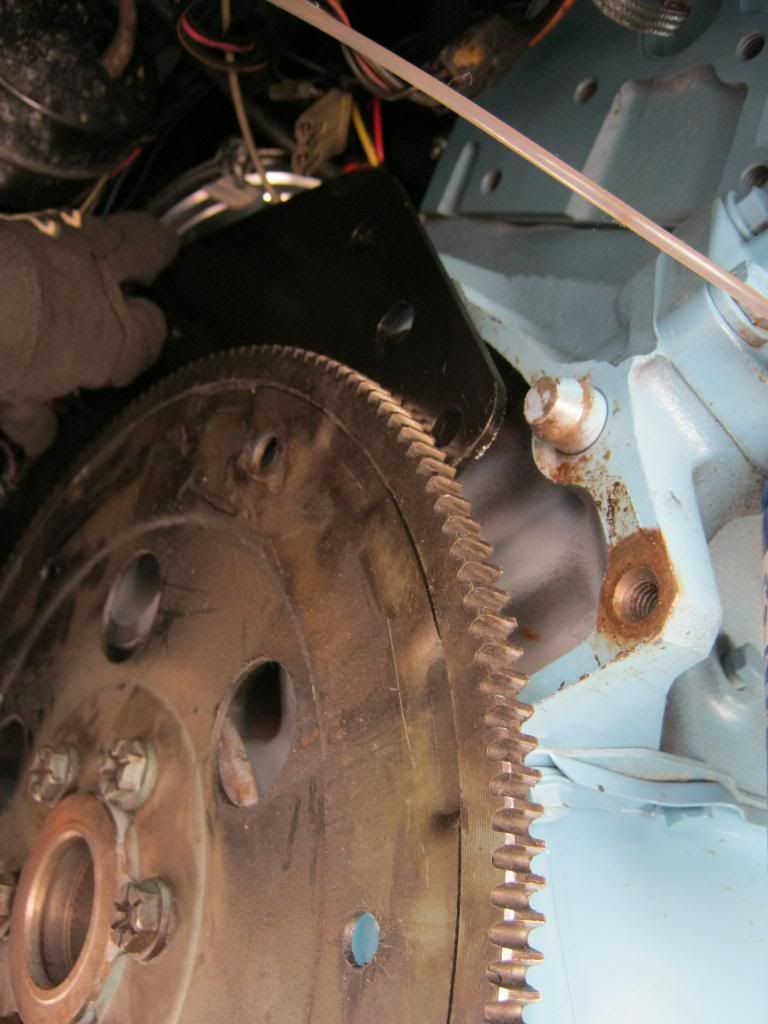
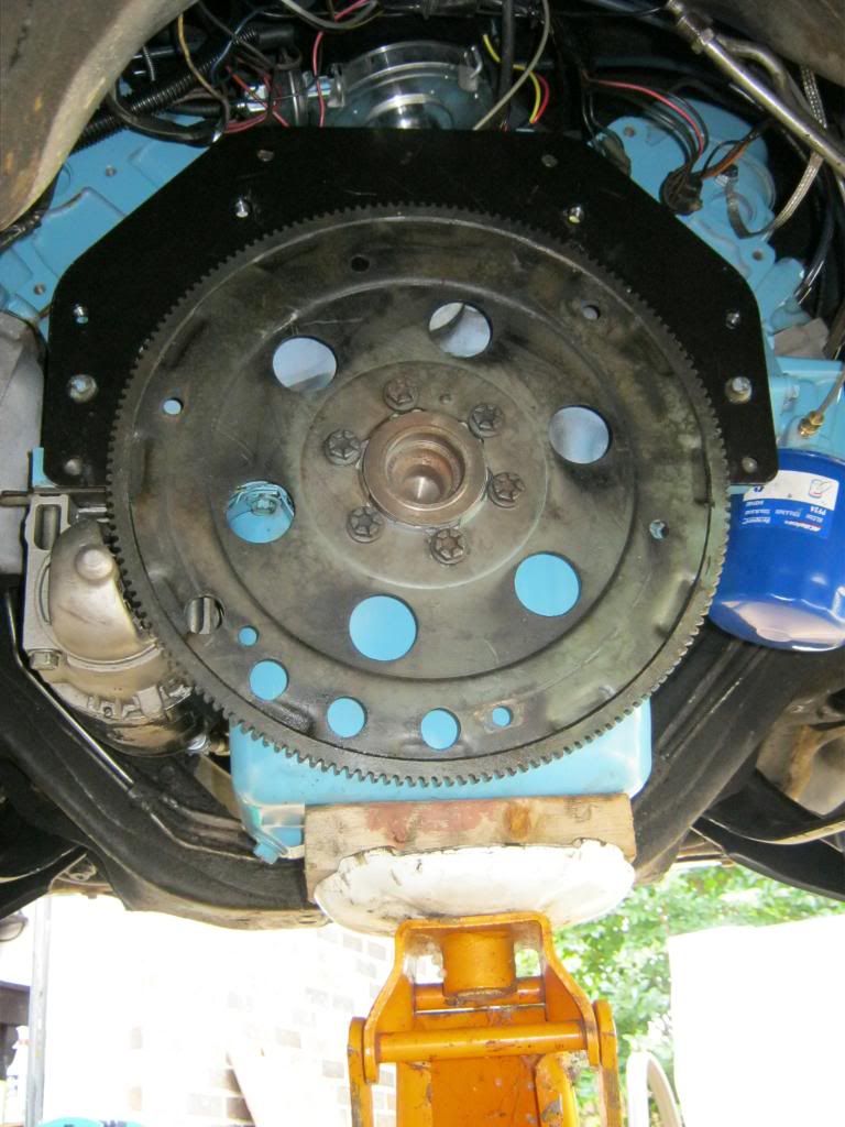
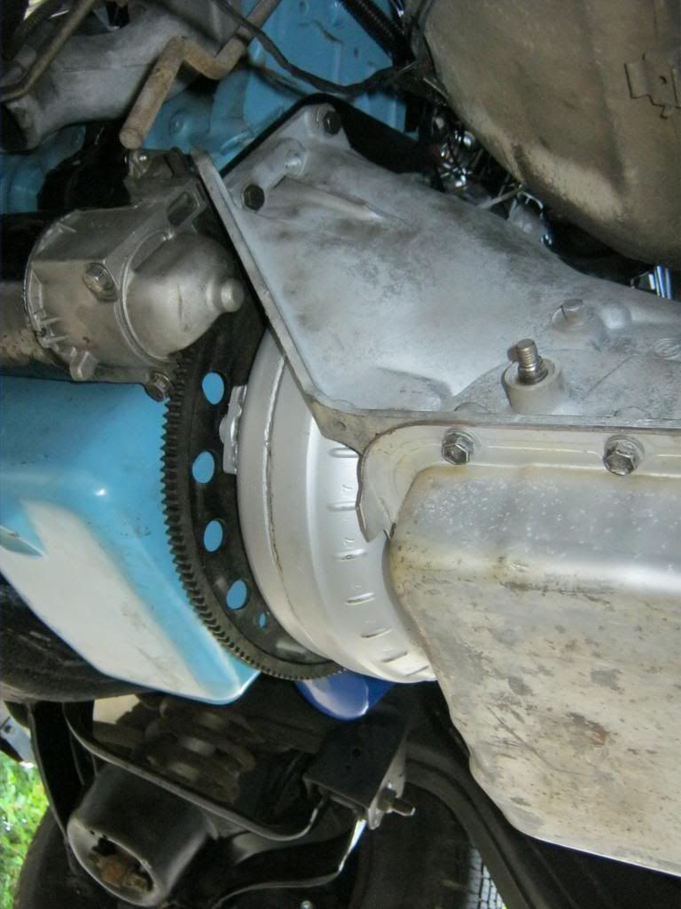
Getting back to the physical mounting of the transmission, I found that there are adapter plates made that will allow a 700 to be mounted to a BOP engine. I ordered one of these mounts, but when I got it I encountered a few problems. First, the mount is supposed to install behind the flywheel, without the need of the flywheel being removed. Because of this I had just installed my flywheel beforehand and torqued the bolts to 95 ft/lbs, along with some blue locktite to keep them from coming loose. As this picture shows, there was not enough room to fit the adapter plate behind the flywheel and over the bellhousing dowels. Because of this I had to remove the flywheel shortly after I had just installed it.

The next problem came when I found that my dowels would not fit through the dowel holes in the plate. I called the company and they said they had never encountered this problem before. I found out from them that GM used a typical 5/8" dowel across the board. Using a tape measure I found the dowel to be 5/8" and the hole to be 5/8" so I knew the difference had to be in the 1/1000ths of an inch. After calling the company that made the adapter and the company that sold it I then measured the dowel holes in the transmission itself and found they, too, were smaller than my dowels, yet they also measured the correct 5/8". For some reason, my dowels were machined too large, but only by a very small margin, and for some reason, my dowels had fit perfectly with the old TH400 I took out. It was with great difficulty I was able to come to this conclusion.


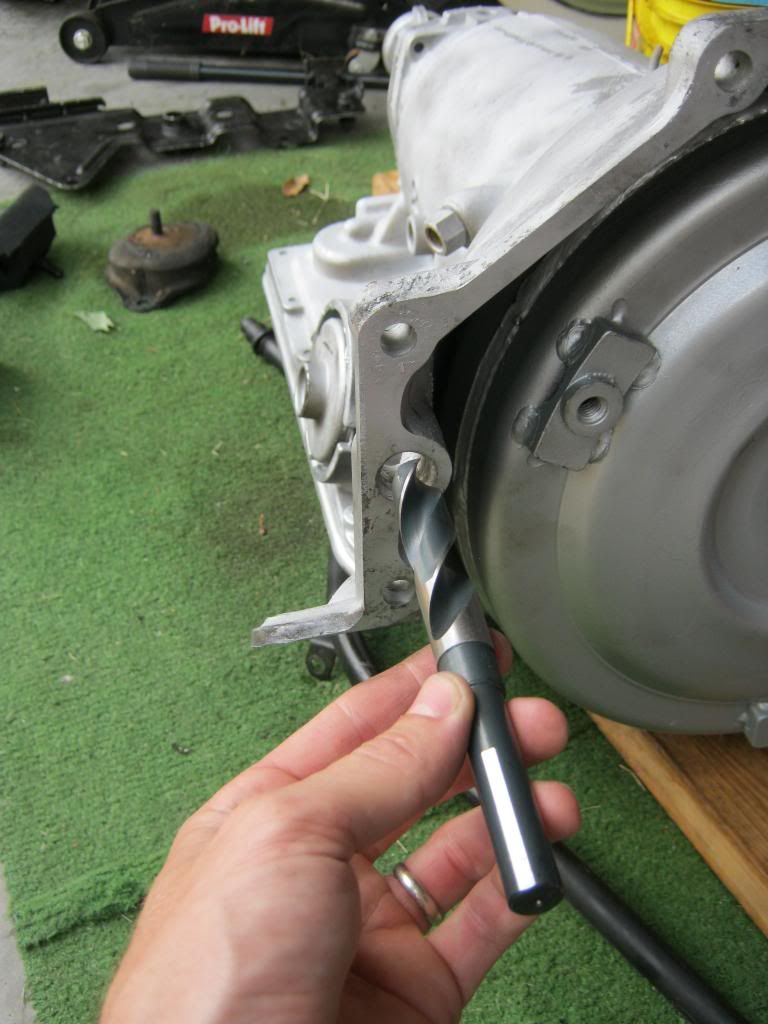
Due to the difficulty of removing engine dowels, my solution to this problem was to drill out the holes in the adapter plate and the transmission. I searched my dad's place for a 5/8" drill bit. He only had one and it was bent. I attempted several other neighbors and coincidentally for one reason or another they didn't have a 5/8" bit, though they had every other size. I ended up having to buy one, and it was almost $20 for just this one bit.
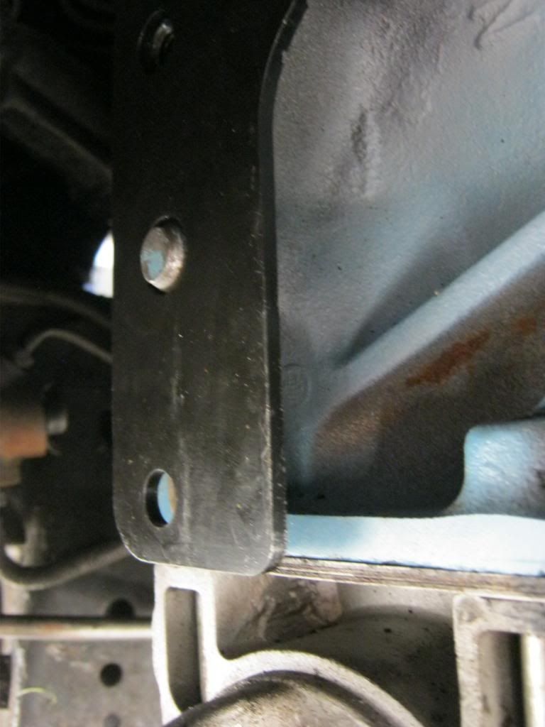
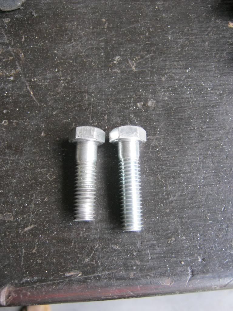
Though not in the instructions I also found it necessary to shorten the top two bolts of the bellhousing because the adapter plate relocates these bolts to fit inside the recess of the rear freeze plugs. At their original length the bolts were between 1/8-1/16" too long, depending on if you measured the left or right side.

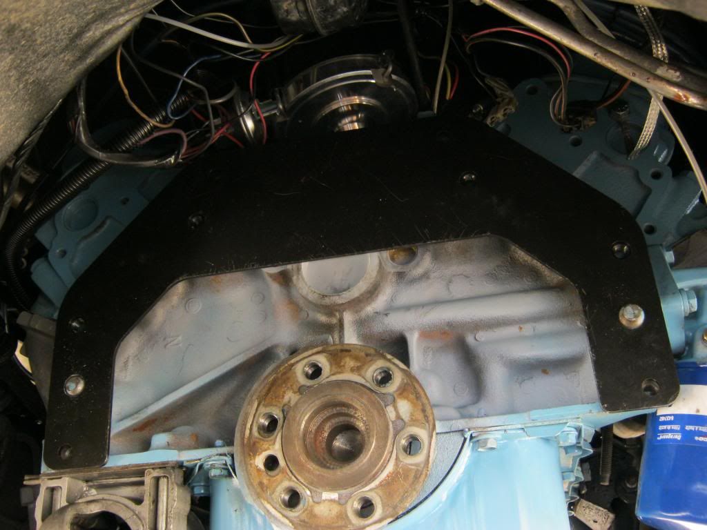
This is what the adapter plate looks like when installed correctly. The bottom holes on each side go directly into the original mounting holes in the block. The second hole from the bottom on each side is the dowel hole. The four mounting holes above that on each side have nuts welded onto the back of the plate. These are the new mounting locations for the 700. The outside two bolts allow the screw to go wide of the mounting surface, so their length is not of any importance, within reason of course. The top two bolts fit into the recess of the freeze plugs and if they are too long will cause damage to the brass plugs. There are two smaller holes, a bit closer together than any of the other holes. These two holes are the original top mounting holes for the old TH400 and are not used to mount the bellhousing. Two round-headed, allen head screws come with the kit and these are installed here to hold the adapter plate.

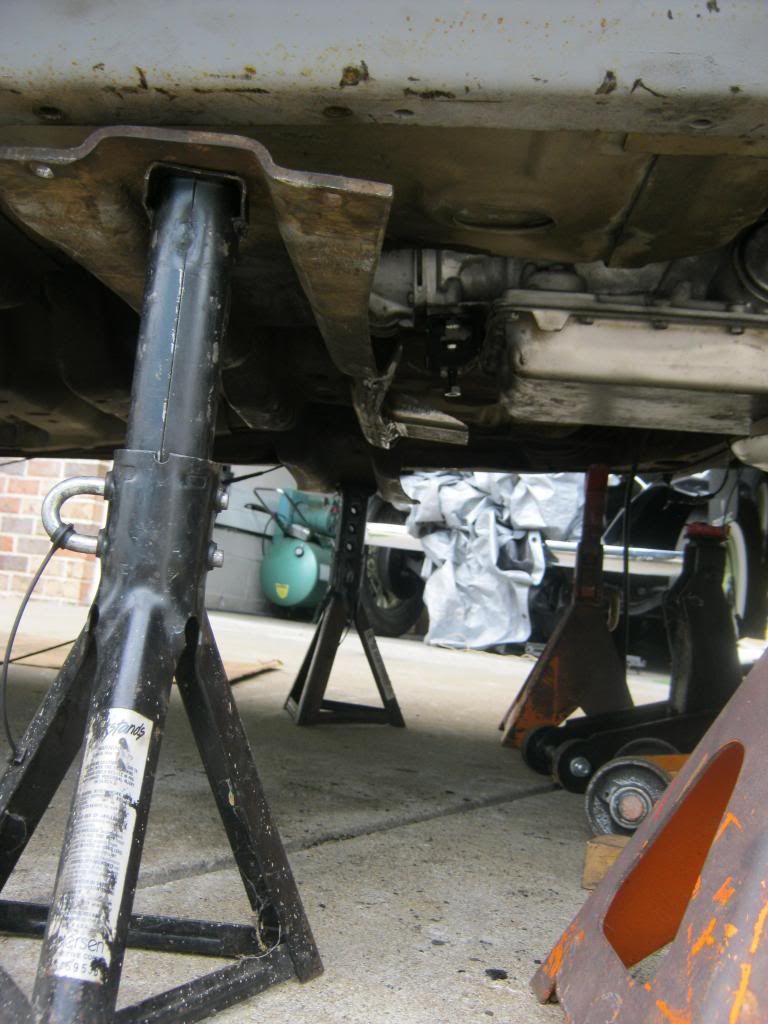
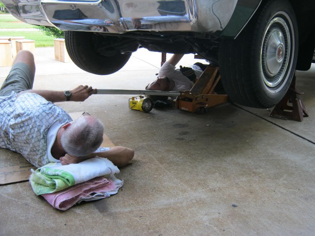
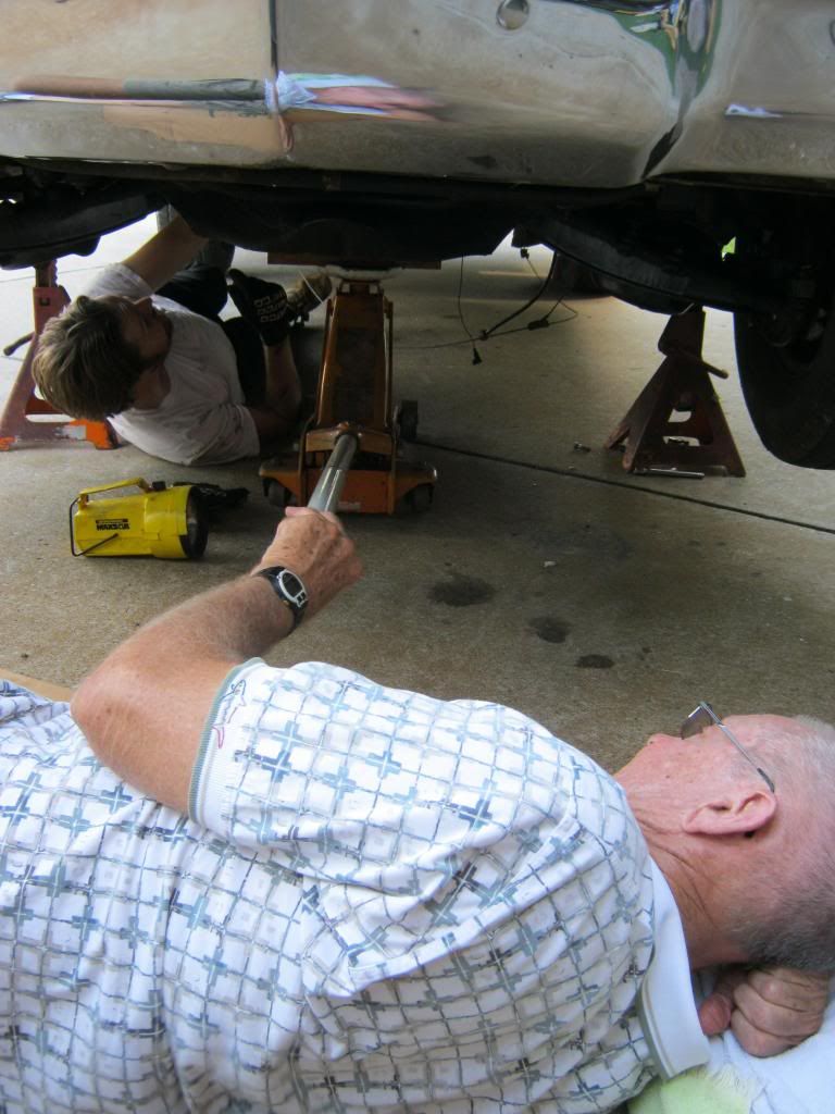
Other than the physical challenges of rolling around on concrete, the physical installation has yet to cause any real challenges. There is plenty of room in the transmission tunnel. The crossmember will require modification, however, but as of now I believe it can be done by slightly modifying the original crossmember rather than buying an expensive, custom one.
While dad manned the jack during installation, April stripped and painted a dresser that will become Rose's changing table.
This is why I have had a crick in my neck for two weeks
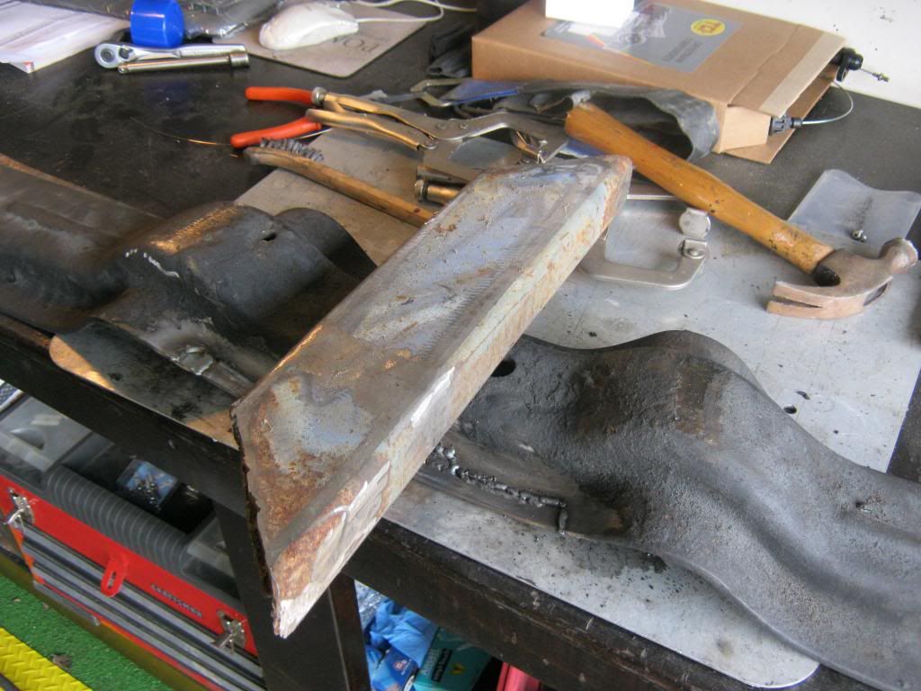
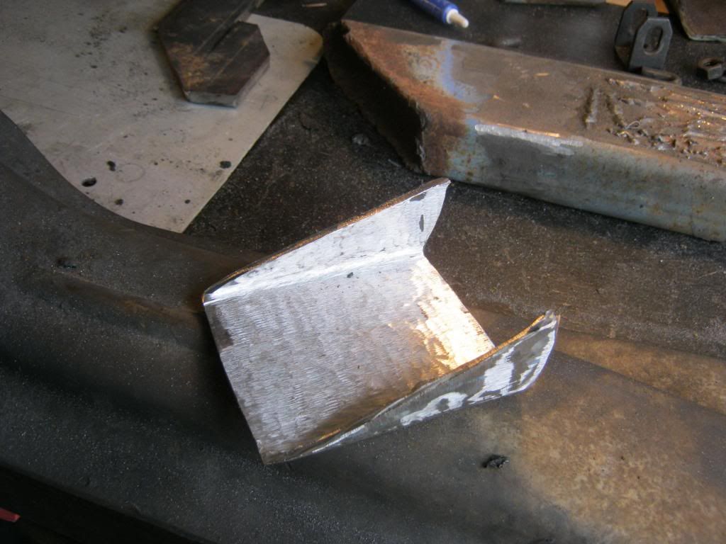
After all of that, I just hurt everywhere from the waist up, but it was time to test fit the crossmember and see what modifications would be needed.
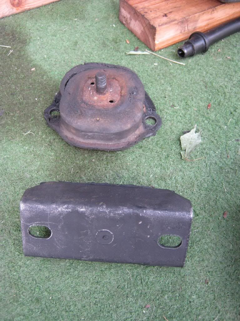
There were everal different tailshafts used on 700R4s, all of which have different lengths and mounting styles, depending on what it originally came out of. This shows the original TH400 mount on top and the new mount that I finally found that will fit my application. Not knowing what this transmission came out of made things a bit harder and would be good information to have before a swap next time.
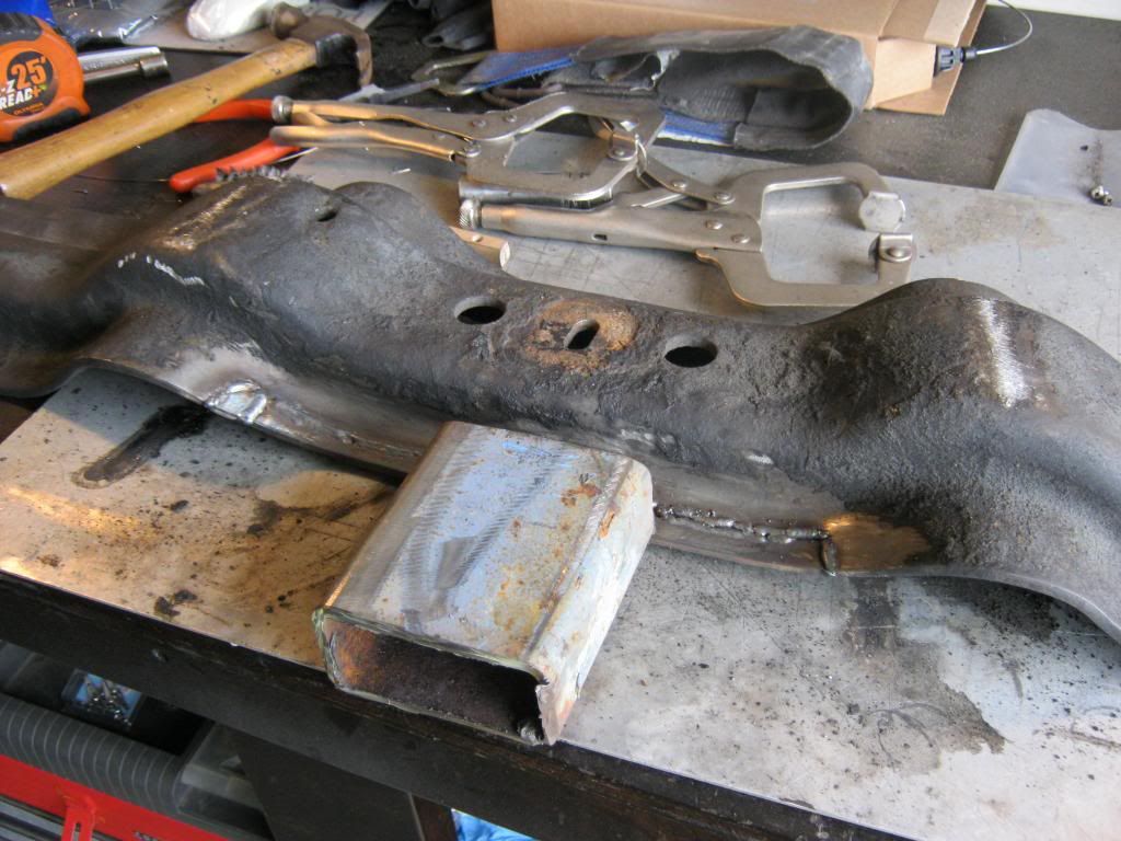
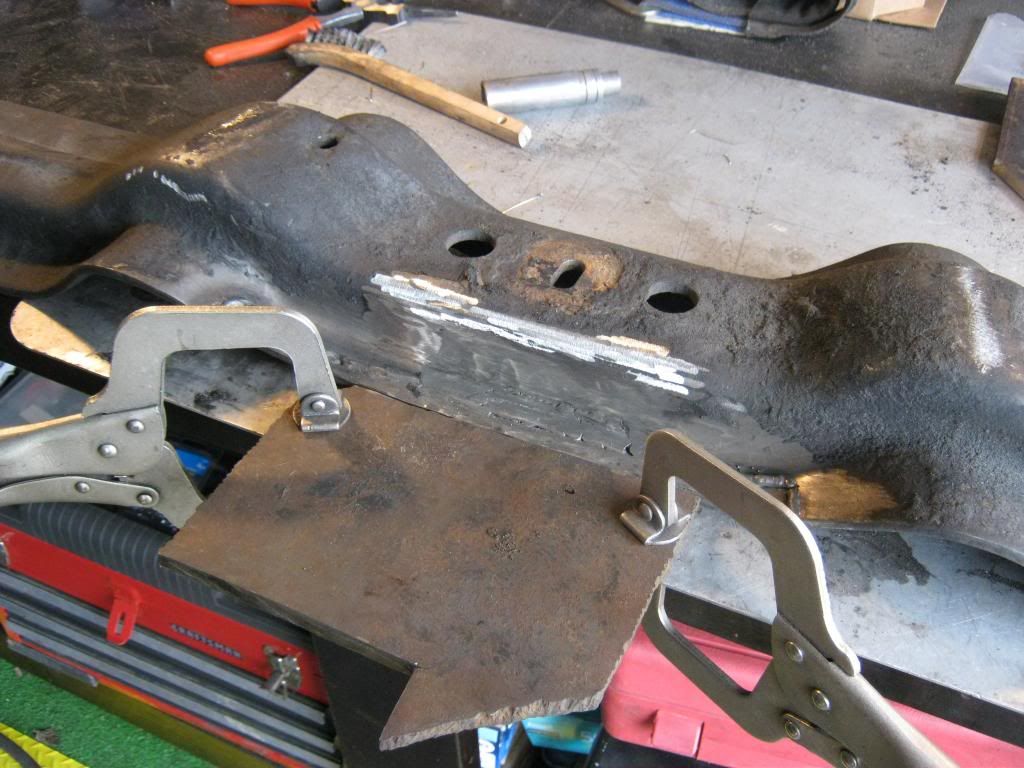
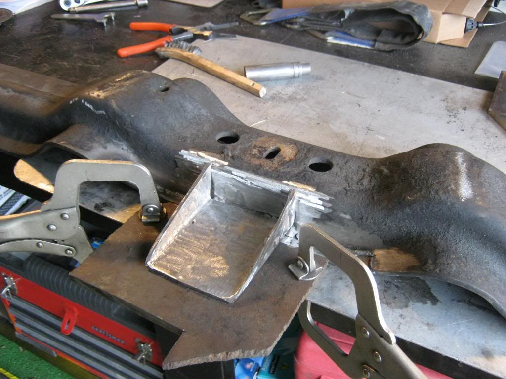
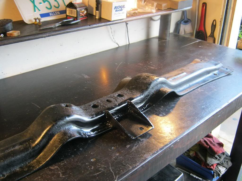
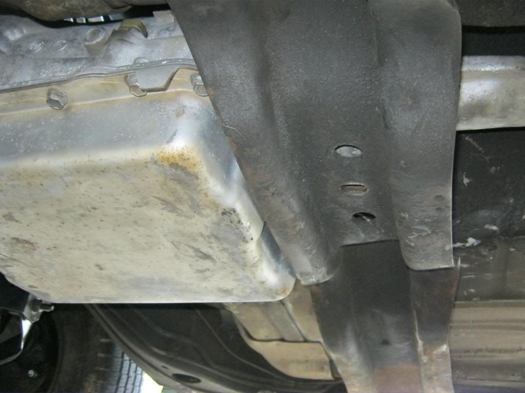
I slid the crossmember forward from its original location, but I was not able to get it to go forward far enough to meet the bolt holes for the transmission mount. It needs about 1/4" more so I will probably have to trim some of the lip away from the front of the crossmember to allow room. When I get it fitted I will then have to drill new holes in the frame to mount the crossmember to the frame.
The transmission is now physically bolted to the engine, but nothing else is complete. I will need to get the crossmember finished before I can get a final measurement for the driveshaft, which I will have cut down or extended to fit.
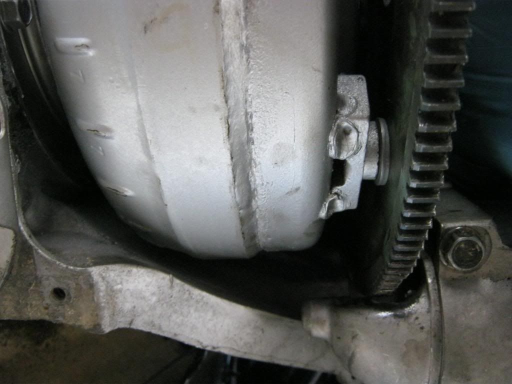
This picture shows the spacers between the torque converter and the flywheel which are necessary to offset the width of the adapter plate. I almost died when I began to bolt my new converter to the flywheel and saw that it would not fit the original holes. I then saw that the flywheel had another set of holes for different applications, so I was able to turn it to the new holes and it bolted right up.