Monday, September 30, 2013

Potpourri

Several smaller finishing touches seem to have no end.  It feels as though I'm finished with the car but there is still much to be finished and it seems as though each time I finish a project two more are added to the list.

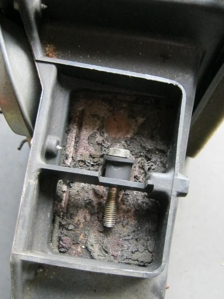
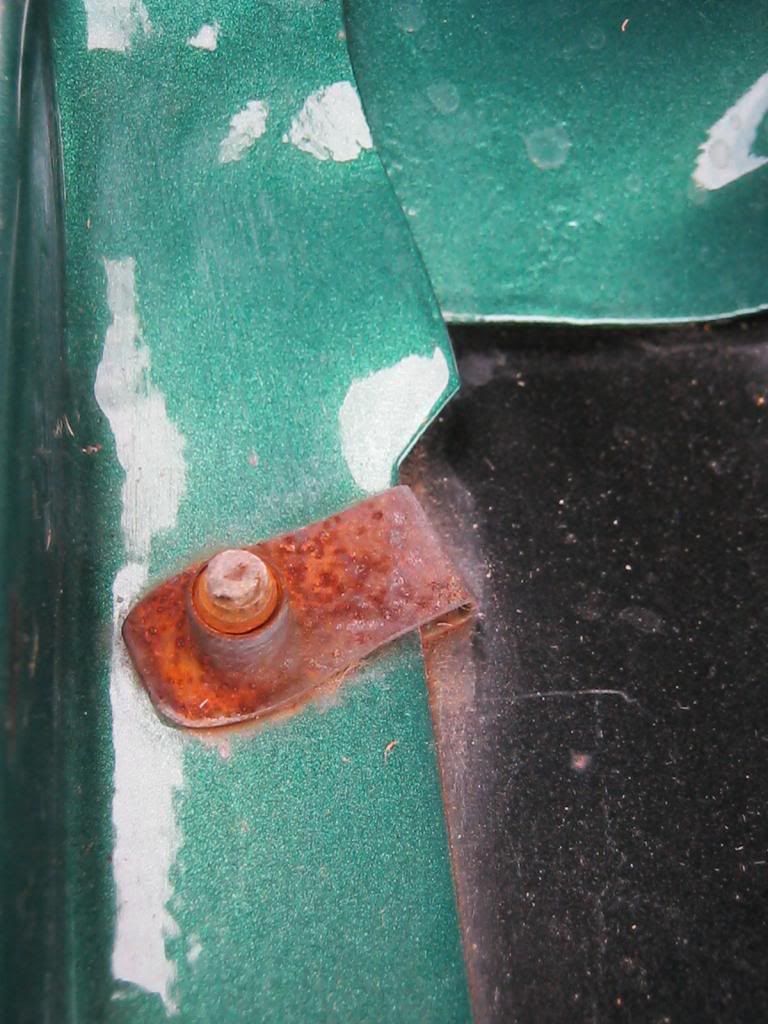
The original clips holding the inner fenderwells were not only a rusty eyesore, but their rust would eventually spread to other places so they had to be replaced.

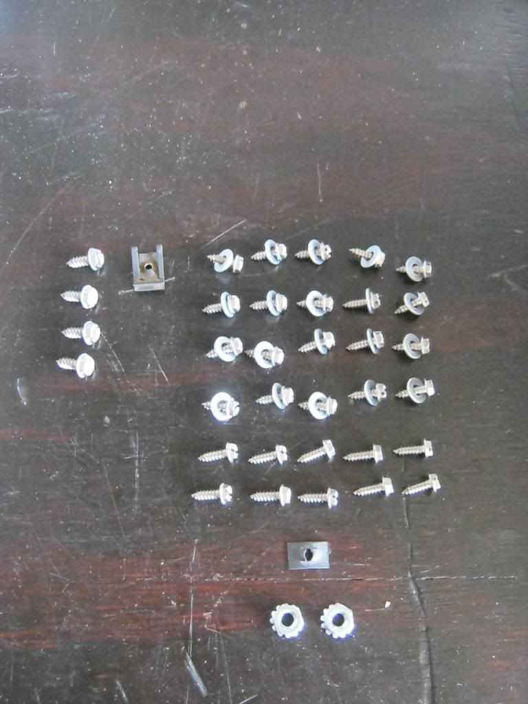
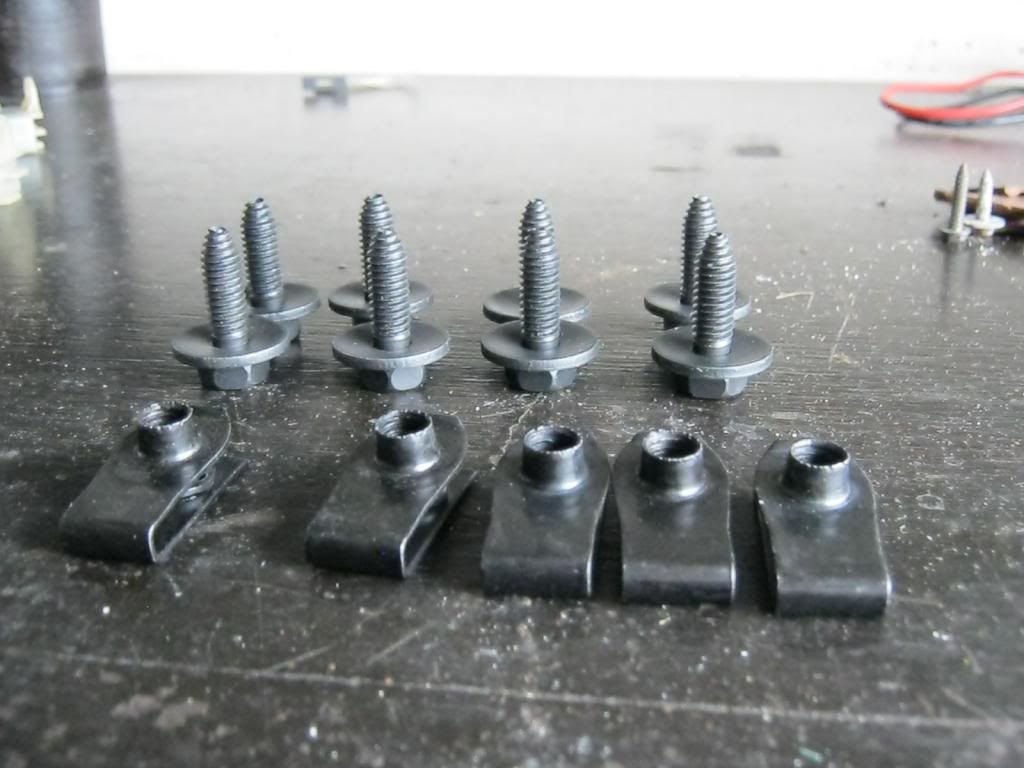
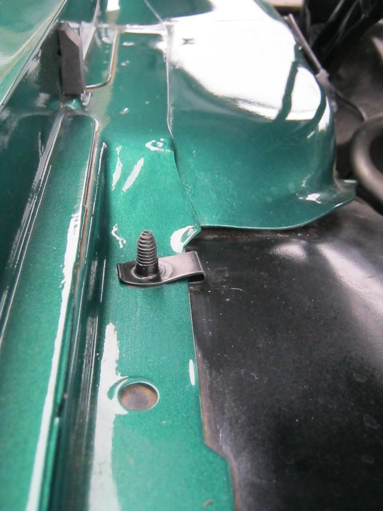
New hardware from the aptly named hardware store.

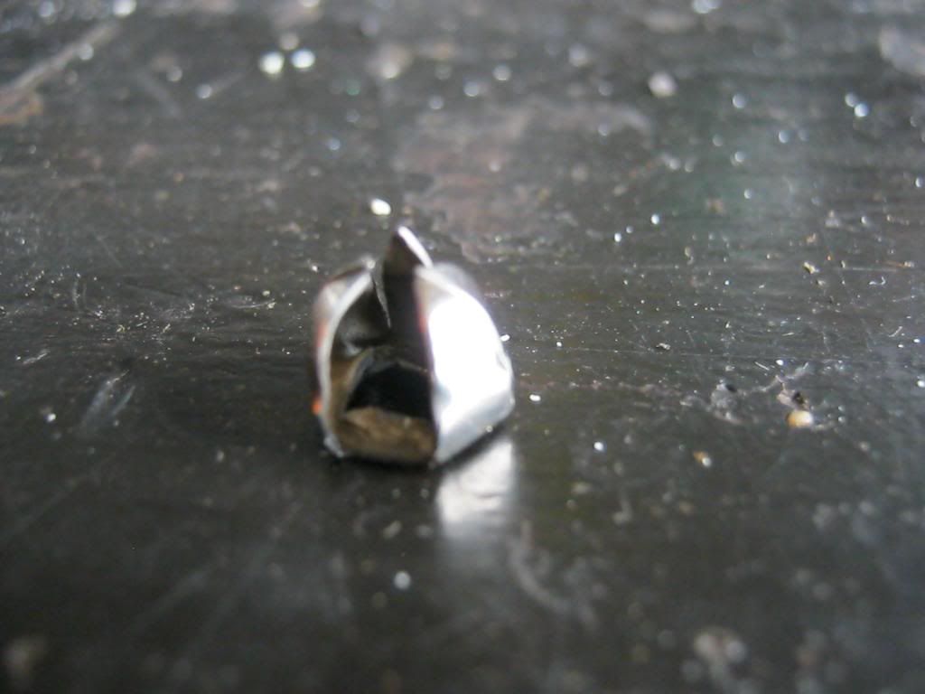
The old rusty clips did not come off easy.  When the bolt is removed the clips have a tab that is bent up into the bolt hole that holds the clip in place and means you can't pull the clip off without pushing that tab.  This seemingly small task turned into a frustratingly time consuming one.

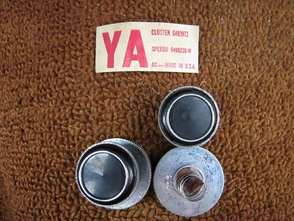
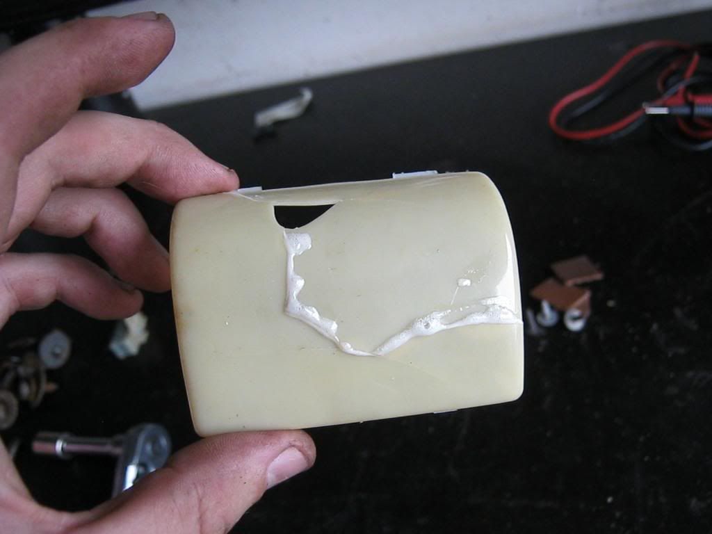
The dome light had a glass lens that had fallen out and the plastic cover was broken to pieces.  As you can see in the picture the lens on the right has a round, metal ring that holds it in place.  The ring was long gone on the left side.  After polishing the chrome dome light housing I used a small amount of glue to hold the lens in place.

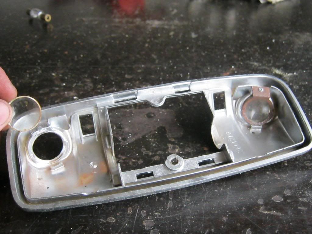
I found the plastic lens in the glove box, broken all to pieces.  This lens is expensive and hard to find so I glued the pieces I had back together.  I found out that Gorilla Glue foams as it dries, causing it to expand and run out of the seams.  At least it looks a lot better than it did with no lens.

At long last I got back to sealing the rear tailgate.  I've been using one of April's big stainless steel pots on one side of the tailgate to catch water when it would rain.  There were only two areas at the sides of the tailgate where water would come in so the pot would catch water on the driver side and I had a piece of plastic propped up on a piece of wood that would direct the drips of water over to the spare tire well where it would drain out the bottom because I removed the drain plug.  This is why I have yet to paint the exterior of the tire well black as it should be.

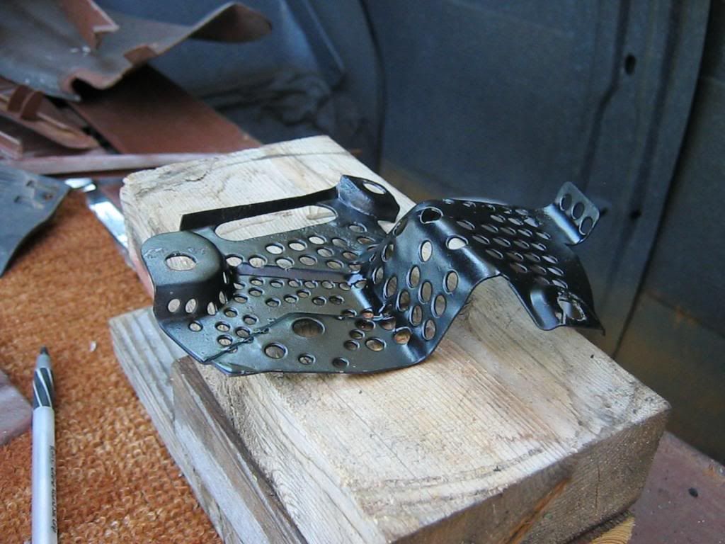
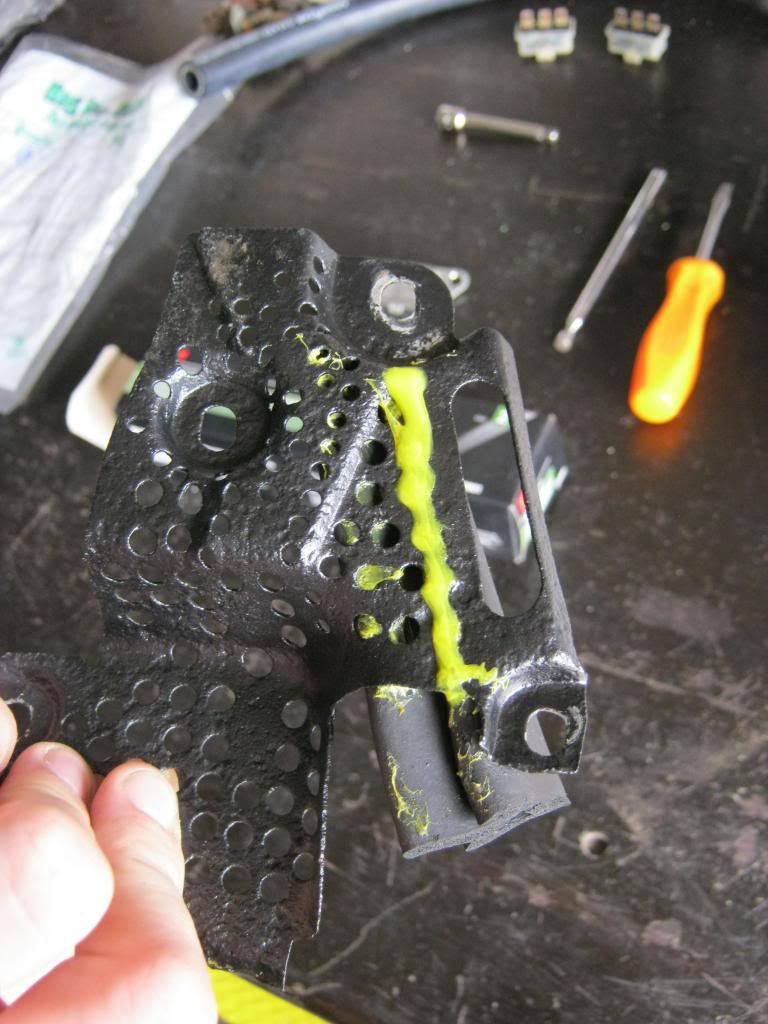
One reason it has taken so long to get to this project was that I had to sandblast and paint the original metal pieces that mount in the top corners of the tailgate area.  Originally these metal pieces were embedded inside rubber but that rubber rotted away long, long ago.  All that was left were the rusty metal support brackets.  I was able to save one of mine but the other was completely rusted.  Fortunately one was donated to me from another wagon enthusiast on the internet.  I forgot to add them to my things to be sandblasted the last time I was at the powdercoaters so I finally called a friend that has a sandblaster and he met me at his cousin's house, where his blaster is, and let me strip the brackets.  After that I cleaned and painted them.  This is one of the two brackets.

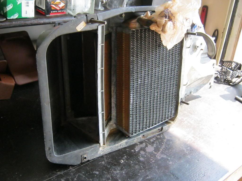
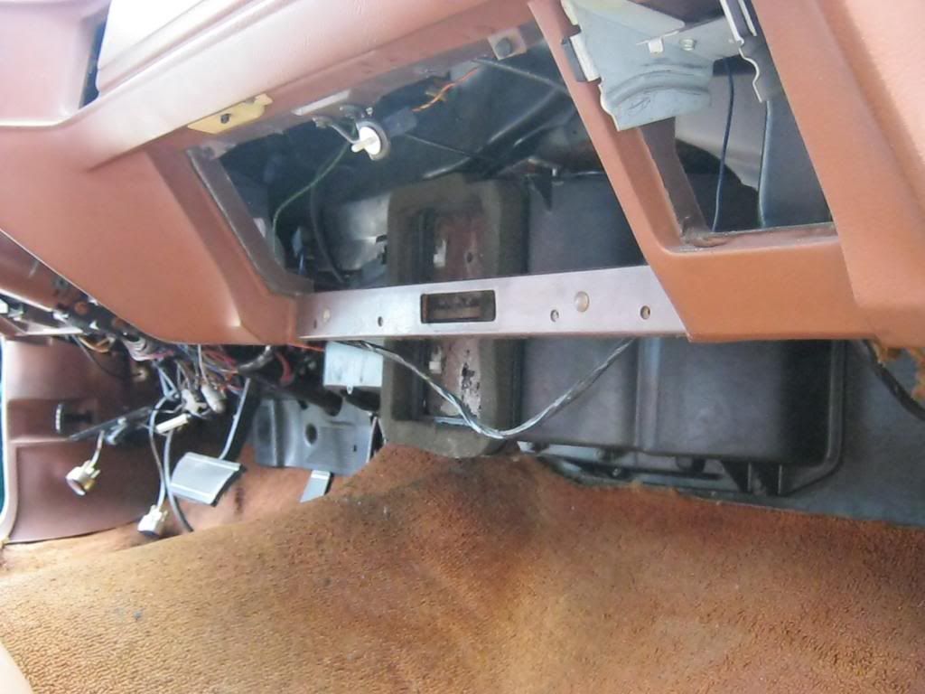
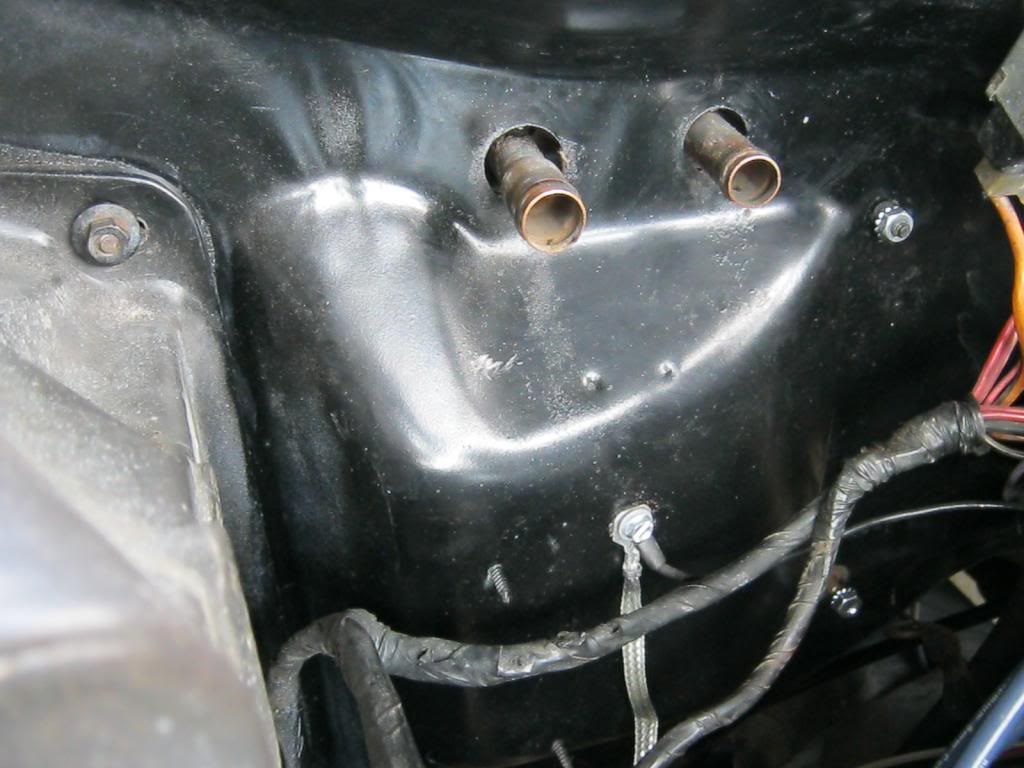
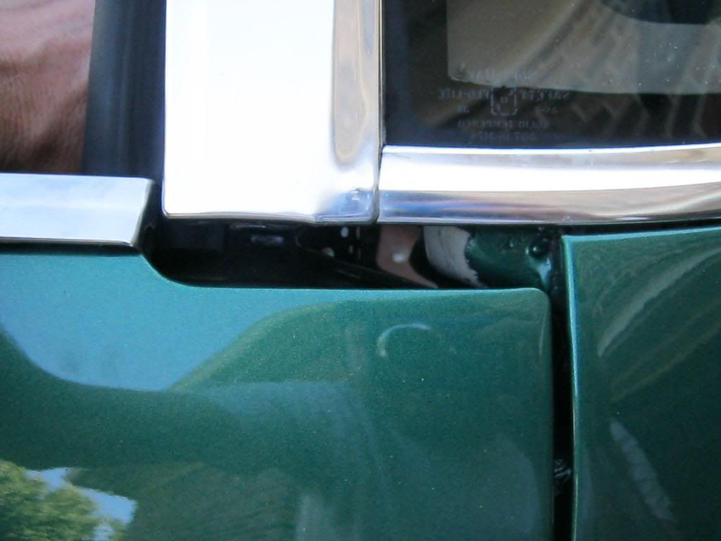
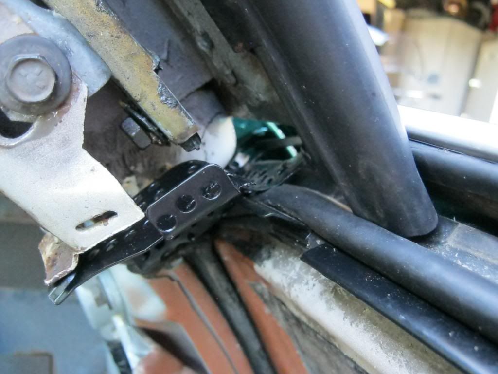
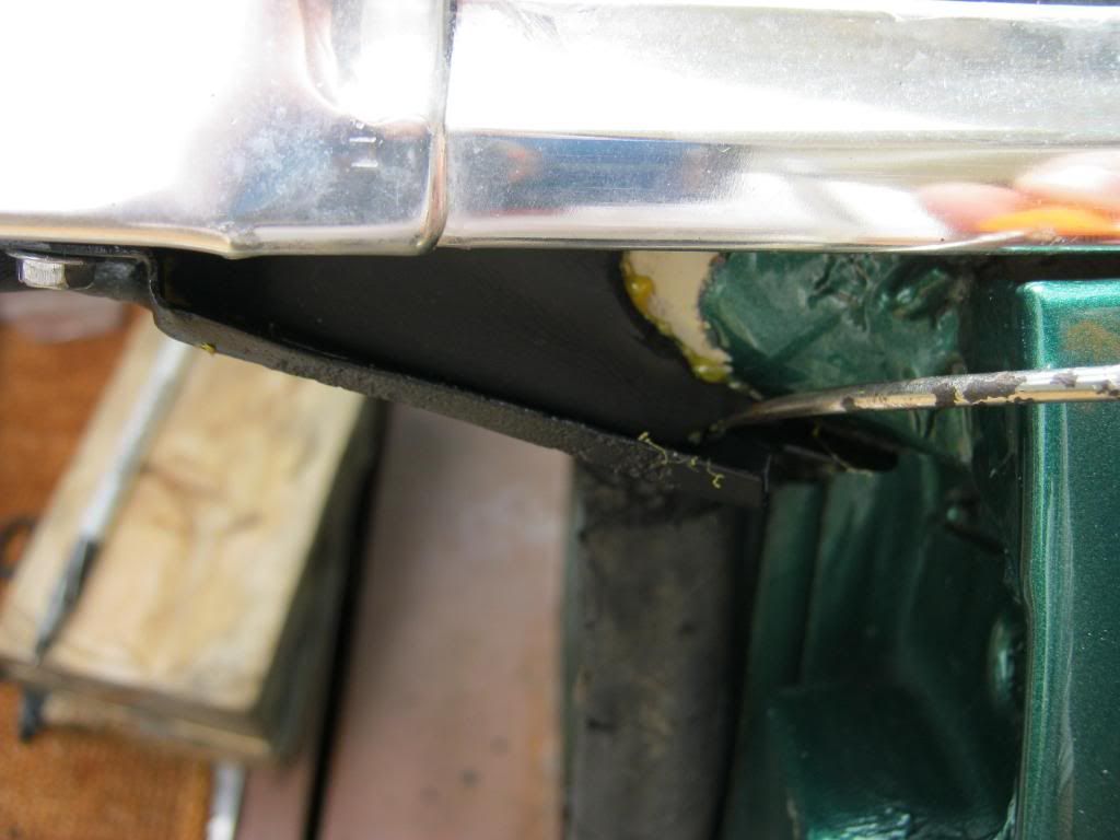
This is the area where the tailgate comes up to meet the bottom of the rear side window and the rear sliding window.

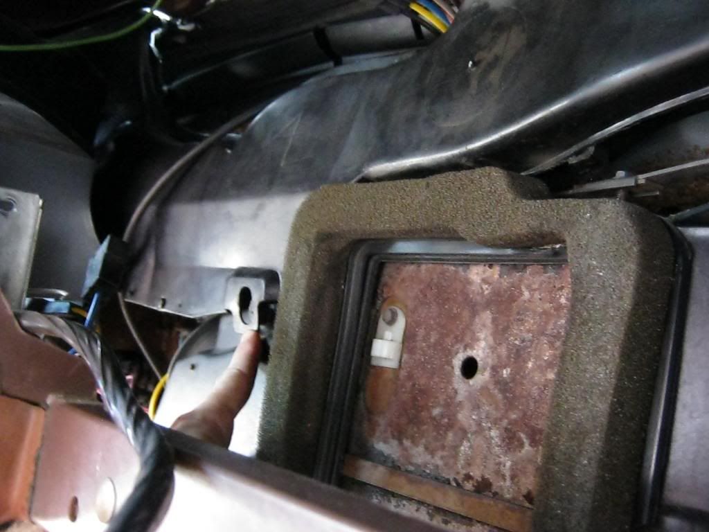
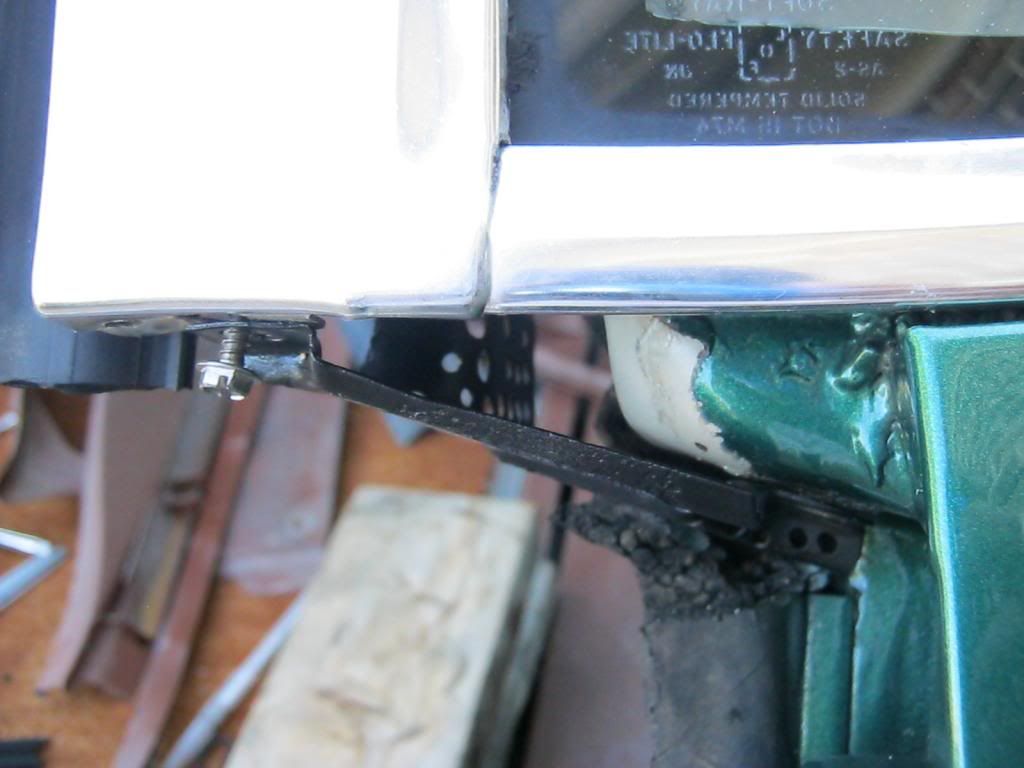
This is the area with the tailgate rolled down.  When the tailgate is raised the weatherstripping I added to the tailgate presses against the bottom of this mount.  I needed to find a way to seal above the mount.

I began by trimming the bottom tips of the left and right rear sliding glass moldings I made a while back.  I needed about 1/16th of an inch or so, just enough to let water drain down them but still run under them, all while also meeting the top of the rubber weatherstripping on the tailgate.

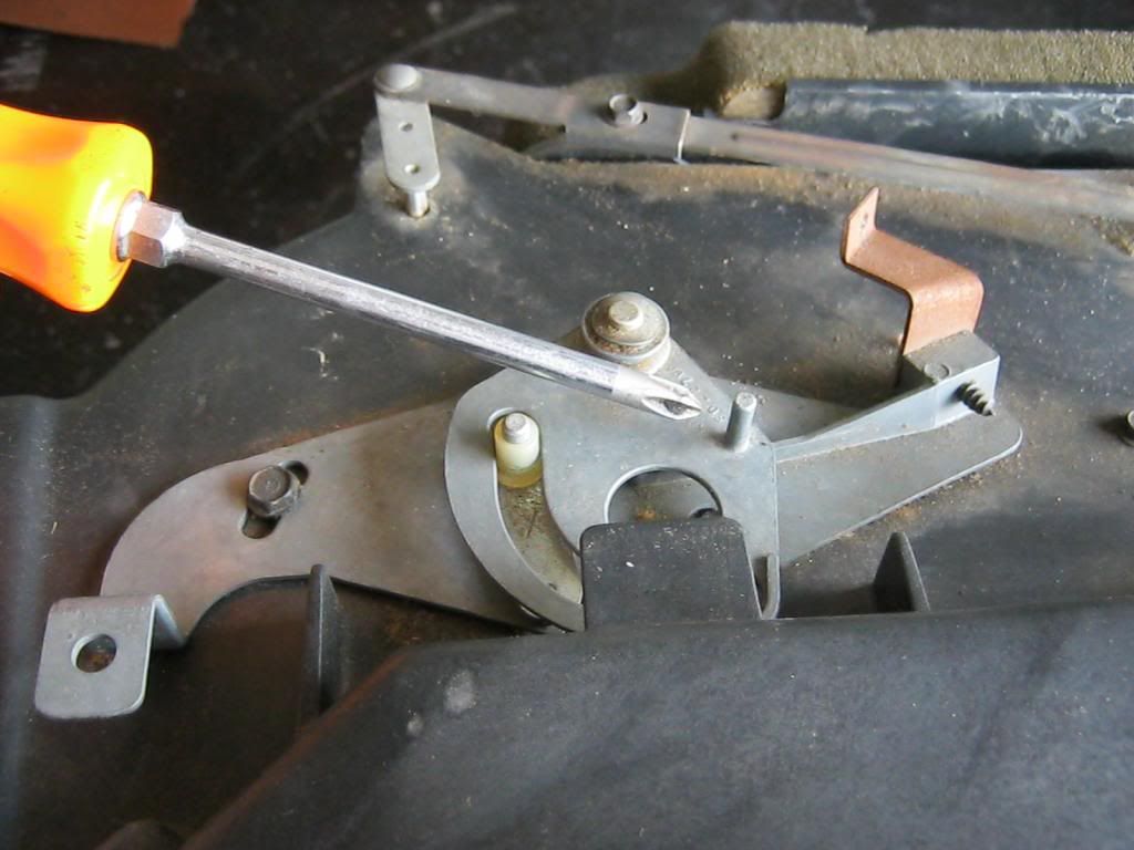
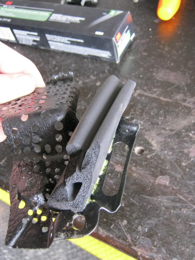
By trial and error I used a piece of the weatherstripping and trimmed and fit again and again until it began to take a shape that would seal when I screwed the bracket in place.  I used weatherstrip adhesive to seal the rubber to the bracket.

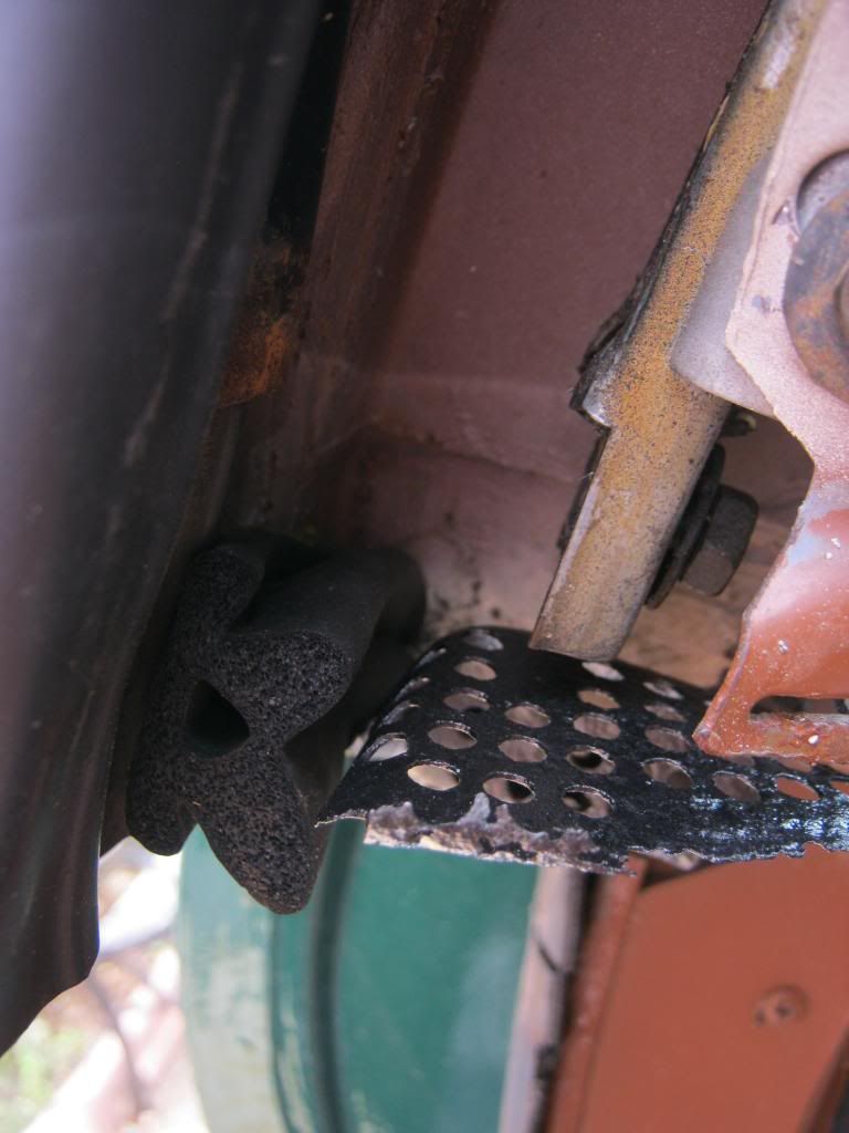
Here are the before and after photos after I finally got the piece trimmed and glued into place.  I'll touch the area up with a paintbrush later.

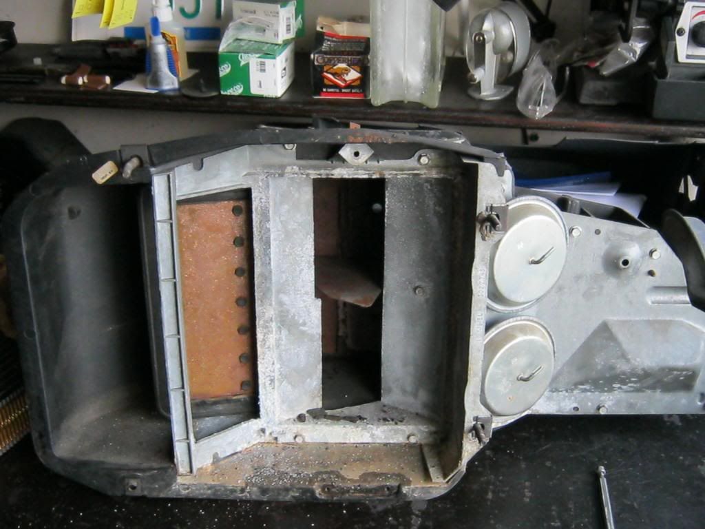
The many holes in the bracket were used in the old molds when the bracket used to be encased in rubber.  I used the new rubber piece I made and covered up all of those old holes except for one.  This will allow any water to drain from this area and down the side of the tailgate as it was originally designed to.

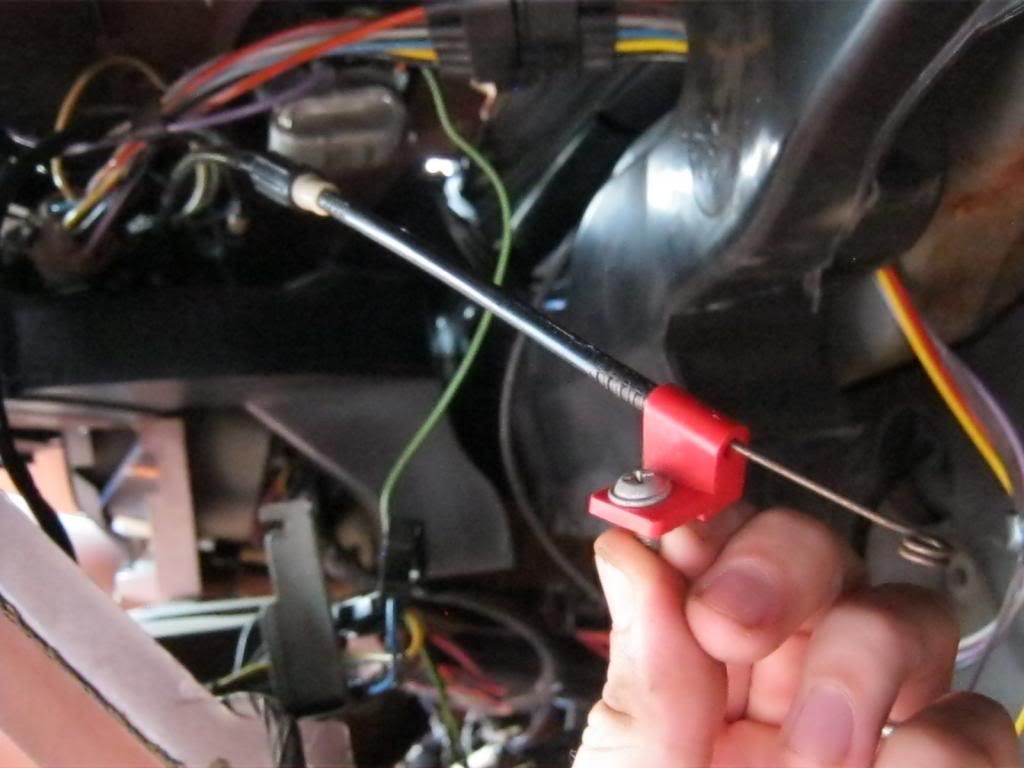
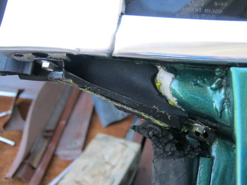
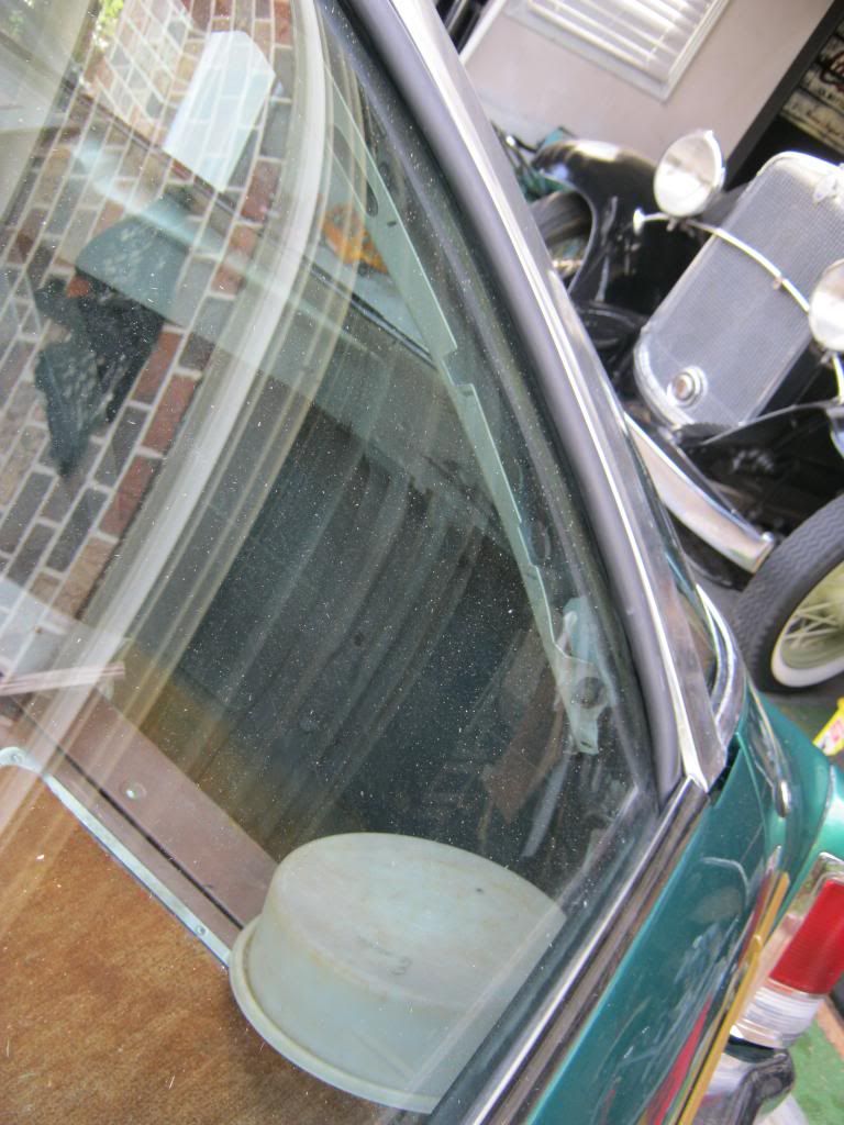
This is a picture of how the new rubber molding looks when the window is closed (I left the tailgate down for better access of the camera).  The inside of the rubber had to be trimmed to match the angle where it would meet the glass.

When the tailgate is rolled up and the window is rolled down it compresses the side moldings between them allowing the water to drain down the back window into the tailgate weatherstripping and then drain to the either side of the tailgate.

After this process I found that the tailgate area still had a couple very small seeps so I'm going to be investigating those and sealing them after the sealant dries on the pieces I have complete thus far.

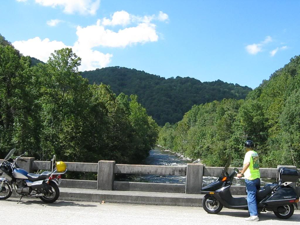
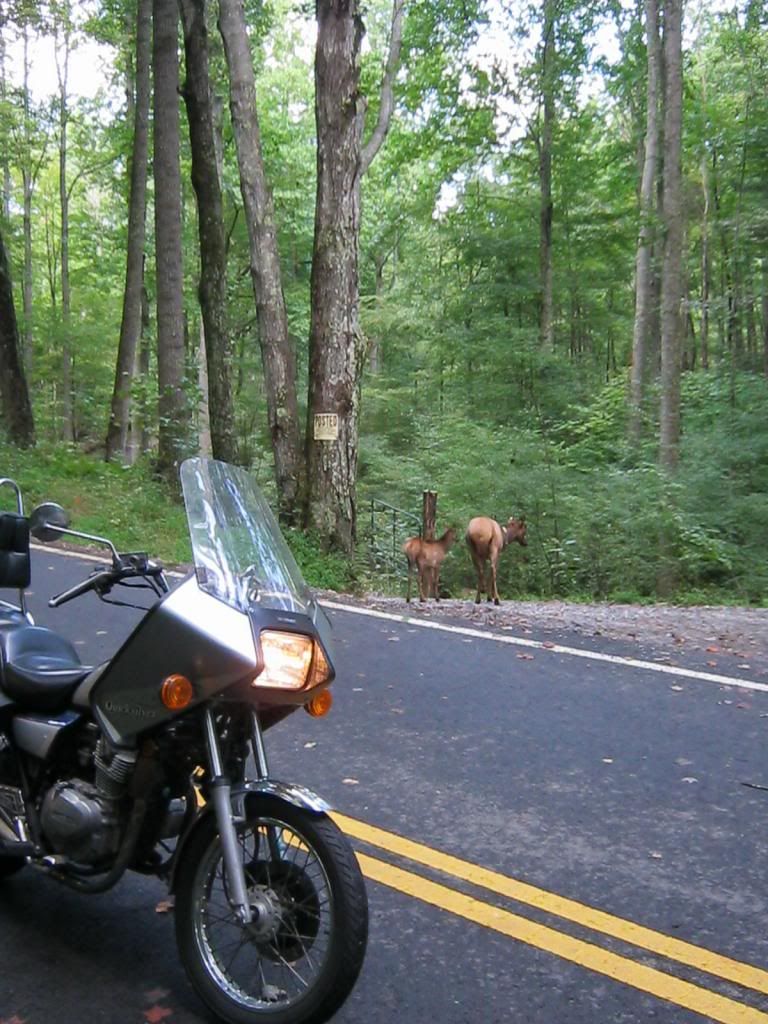
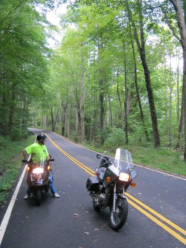
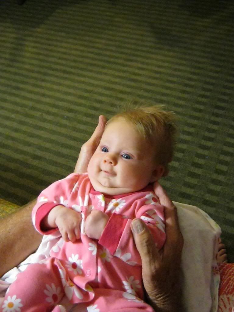
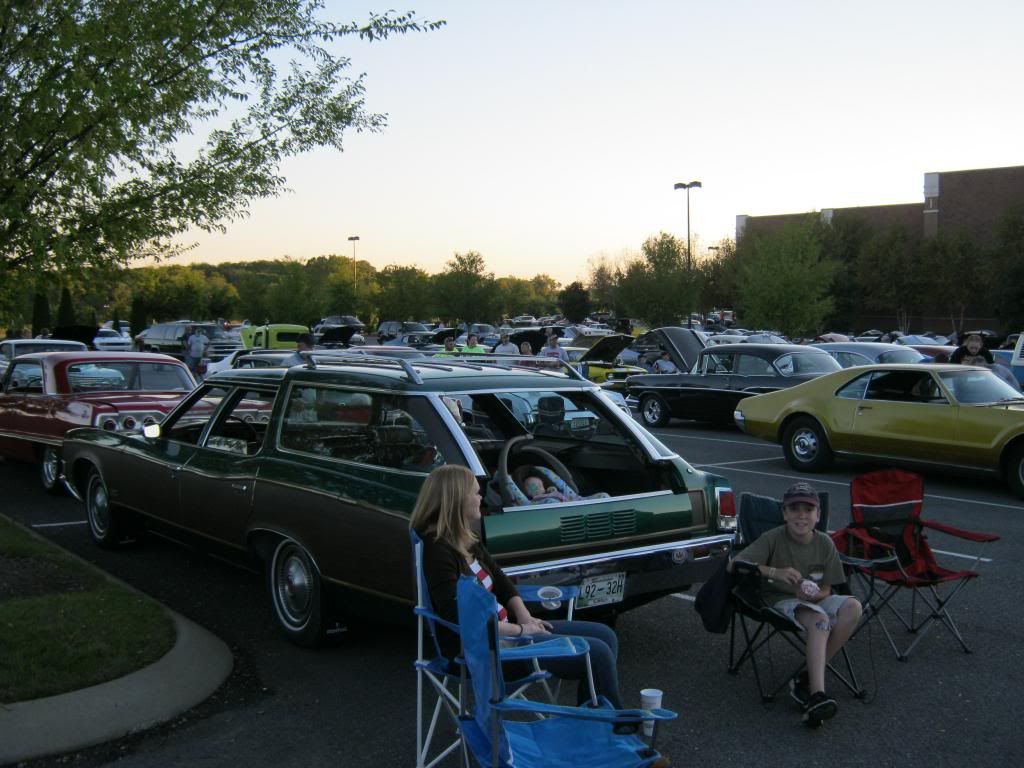
Despite the fact The Clam isn't completely finished we had the opportunity to make it to the local cruise in.  Since this may be the last time this year we get to go we decided to debut The Clam.  Jacob called before we left to see if he could go with us.  The tailgate area worked great for Rose.  We sat her car seat in the back and kept the tailgate up just enough to keep her from possibly falling out.

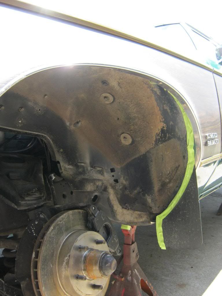
Another project that I finally was able to get to is cleaning and painting the fenderwells and the bottom of the frame under the rocker panels.  The frame in this area had some bare areas from sandblasting which had caused some surface rusting.

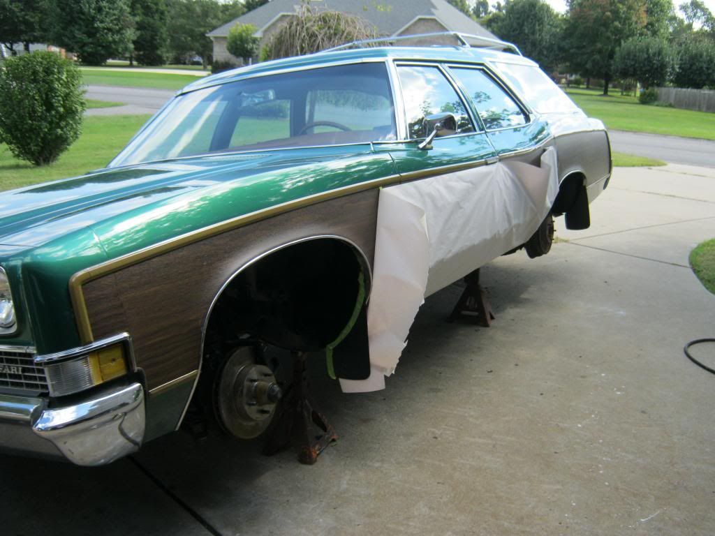
I thoroughly cleaned the fenderwells and then came back over them with brake cleaner to prepare them for paint.  Then I taped off the area.

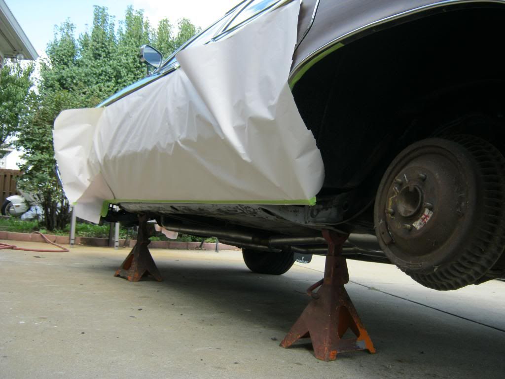
I used a grinder pad on my air grinder to strip the worst areas on the bottom of the frame and then finished the rest with scotch-brite pads.  Then I prepped them for paint and taped off the area.  I was only able to get the driver side done today so I will have to finish the passenger side tomorrow.

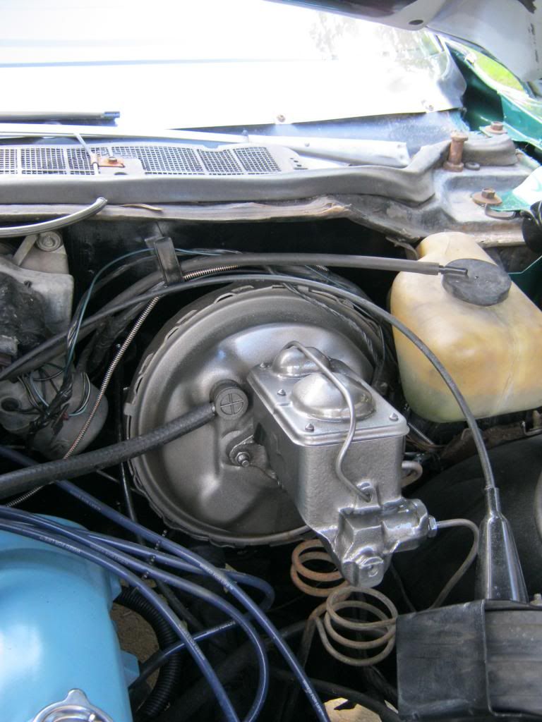
The new master cylinder had some rust on it from where brake fluid had run over when Nick and I went through the terrible time we had bleeding the brakes.  I used the scotch-brite pads to clean the part and then repainted it with a cast iron colored paint.

Thursday, September 19, 2013

The Clam Is Not an Old Blow Hard

I really, really wanted to get The Clam finished so we could take it on our vacation to Pigeon Forge to the Rod Run, a car show that floods Pigeon Forge each year with literally thousands of cars lining the strip.  Unfortunately my run down feeling for the past two weeks had turned into a fever which kept me from making any progress the entire week before we left.  I was sick the first few days we were there but eventually got better and well enough to take a bike ride with dad through the mountains.

We got to see a kayaker get swept away in the rapids and float down river.

And then some kind of animal, which may have been a caribou, tried to make us an endangered species by taking the right of way.  They definitely weren't deer and they had collars around their neck with electronic tags.

And Rose got to experience her first trip to The Smokies and her first massive car show.  Unfortunately we had to pull over and stop when she had a "massive blowout" of her own.  Seriously, it was terrible.

And she got to smile for mom and dad for the first time.

But, enough of why I haven't been working on the The Clam and onto what I have finally been able to get finished.

The high blow on the fan does not work on The Clam.  The fan motor has two separate systems for speed.  On this particular year car there is no off position for the fan.  It blows continuously on low anytime the key is on as part of a ventilation system GM had designed.  The first three settings of the fan blower speed run off of resistors and the high blow setting has its own relay.  Using the manual I located the master relay and high blow relay but have not yet checked the relay to determine if it is the problem, which I suspect it is because I have checked all of the fuses.

The heat and air system on The Clam was a complete mess.  These cars from the 70's have always intimidated me with their endless labyrinth of vacuum lines and interwoven wiring, most of which is so brittle that little more than a touch causes them to crumble away.  When we bought The Clam the entire lower ducting system was in the back of the car and the switches on the dash didn't work.  I have been dreading when the time came to deal with them, but it eventually came anyway.

I didn't bother documenting the process of removing the system because whoever had installed it, if you could even call it "installed," had everything so messed up it was pathetic.

This is the front and back of the heater core core case.  You can see that the vents are covered in rust and had some kind of flaky material that wanted to go everywhere so I vacuumed the entire case and cleaned it all before reinstalling.

The two round silver objects and one black on the right are diaphragms.  When suction is applied to them via vacuum lines they open flaps which are connected to them via rods.  The top diaphragm controls an upper flap on the front of the case and the lower diaphragm controls a flap on the bottom of the front of the case.  The on on the right controls the defroster vent flap.

One of the many things wrong was that someone had hooked all of the vacuum lines into the wrong diaphragms.  What tipped me off is when I began searching behind the encasement, before I removed it, I found the red line unattached and it didn't appear to have enough length to reach any of the locations it should fit.

The shop manual was very useful for a change.  The information was scattered over about 80 pages, with other models also thrown in the mix, but if you read through the entire chapter you would find certain key pages that if you connect the information would allow you to deduce what you needed to know.  This vacuum diagram indicated the previous mechanic's stupid mistake.  The line labeled "Tan" is in reality a "Brown" line.

The way that this system works is that air enters from the cowl and goes through the firewall at the top right of this picture.  The diaphragm that you can barely see in the top right will open on the "Max" setting, which is also the "Recirculate" setting, blocking off most outside air and allowing inside air back into the system.  Under all other settings, the door closes and allows air from outside the car to enter the cabin and then goes through passages and comes out though this vertical, "D" shaped hole in the firewall.

Then the air enters the encasement through the opening on the left, seen here.  The door in this picture is closed, which directs the air through the heater core, which warms the air, and then it continues out of the front of the encasement through the upper or lower flap, depending on how you have positioned your selector.

When the flap is moved to this position the heater core is blocked off and the air bypasses it, going straight through to the front of the encasement and out the upper or lower flap.

Here is a picture without the heater core to show where the air goes after it has passed through, and been warmed by, the heater core.

The hot/cold selector on the dash controls this main flap via a cable that connects to the top of the encasement.  I found that this cable was not even connected.

The hardware store didn't have anything that would work to keep the cable from sliding off its pin so I had to modify a pushnut to hold it in place.

This is the defrosted vent flap, which can be seen on the left side of the first picture I have of the case.  If desired, doors inside the encasement can be opened or closed in such a way as to direct the air to this flap on the top of the encasement and then to the defroster vents.  When I removed the encasement I found that this bolt had somehow been wedged between the flap and the encasement, preventing proper function.

Almost all of the hardware was missing and it took me half of the morning to determine what size and how many of each screw I would need to complete the task.  This is almost $10 worth of stainless steel hardware.

After taking the heater core to a local radiator shop and having it tested for leaks I reinstalled it in the case.  I hooked the vacuum lines back to their proper location.  Here you can see the upper and lower flaps on the front of the case.  These flaps direct air into the main lower ducting.

Out on the firewall you can see the three screws that hold the case in place.  These three screws are on the top left, top right and bottom right of this picture.

Another issues was that when we got the car the case was not properly seated against the defroster vents.  The tab where my finger is pointing in this picture was completely inside the opening on the case, of course with no screw holding it in place.

After finishing the case I moved on to installing the upper vent ducts I had removed.

One day while test driving the car the radio began to play.  It lasted for several minutes then quit.  The AM/FM selector was loose and I thought that perhaps it may be the issue.  I took the radio apart and manually put the radio in the FM position, but unfortunately it did not fix the problem.

The back of the radio has a lot of connections going to it.

When I took the radio out I found this tag which gave information about what speedometer and cluster were in the car.  I found it pretty interesting.

I reinstalled the radio and bottom ducting but found I had to remove them again to get access to the screws that connected the upper ducting to the lower ducting.  Unfortunate and time consuming, but at least I know it's done right, unlike the last person who halfway hacked it all together.


When I was testing the heater core flap I noticed it did not line up correctly when pushed to full cold or full hot.  I found that this item I'm pointing to was an adjustment.  I had turned it when removing everything because I thought it might be a disconnect for the cable.  Turns out it was an adjustment for cable length and I had gotten the line out of adjustment.  A little playing with it and I was able to get it set correctly once again.

After a good cleaning I reinstalled the bottom ducting, which of course didn't go in any easier the second time I put it in.  It's all a very tight fit.  Another reason I had to remove it was that I didn't realize the bottom heat distribution duct, a smaller piece of black plastic not seen in this picture that would sit right on top of the transmission hump, cannot be installed after the main lower ducting in in place and must be installed first.

Then I put the crossover ducting that goes under the steering column and connects the upper driver side vent to the main ducting.  It also connects the driver's awesome crotch vent.  April and I both love these vents, driver and passenger, on our 70's cars and we can't understand why they stopped putting them on cars.

Then I reinstalled the ashtray support.  Both top screws were missing and only the bottom, horizontal screw was holding it in place.  This explains why the ashtray was loose and had a lot of play in it.  The entire bottom part of the dash was also loose due to many missing screws.

And finally I reinstalled the smaller things like the beloved crotch vents.  Seriously, why did they ever decide to stop making these.

I can't stress what a pathetic job someone did on this system.  I can't tell if they were lazy or just stupid.  I hope the older lady that originally had the car didn't pay someone for this work.  I suspect, though I have no proof, it was probably the guy who had the car before me.  From the way he talked and the little I saw of his work it seems to fit.

In the end the air finally blew out of all the right places when it was supposed to except for one.  The only issue is that this car has two settings for the defroster vents.  One is called Defog and the other is called DeIce.  The defroster vents work for DeIce, but they do not work for Defog.  Since ultimately there is very little difference between the two I do not feel it is worth completely tearing down the entire system and replacing parts until I fix it when these two features, for the way we would use them, are practically redundant.

The car also has a "Max" setting that is unique and I have not encountered on another car.  Typically a car has a Max setting which can be selected and this recirculates the inside cabin air.  This is why sometimes a car will have "Recirc" instead of Max, because they are the same.  Typically Max is an independent feature and you can select it on and off at any time, but on this car Max is selected by moving the temp selector all the way to the farthest cold setting.  At the end is an extra "click" and when that is selected the car goes to Max and the fan speed is overridden to be on the highest setting regardless of where you put the fan speed selector.  I won't know if this feature is working properly until I get the compressor charged and blowing cold air.  I sincerely hope it works because from what I have seen trying to break down and understand the wiring of this process would be something I would truly hope to not get myself involved in.