Thursday, August 30, 2012

Jigsaw Puzzle

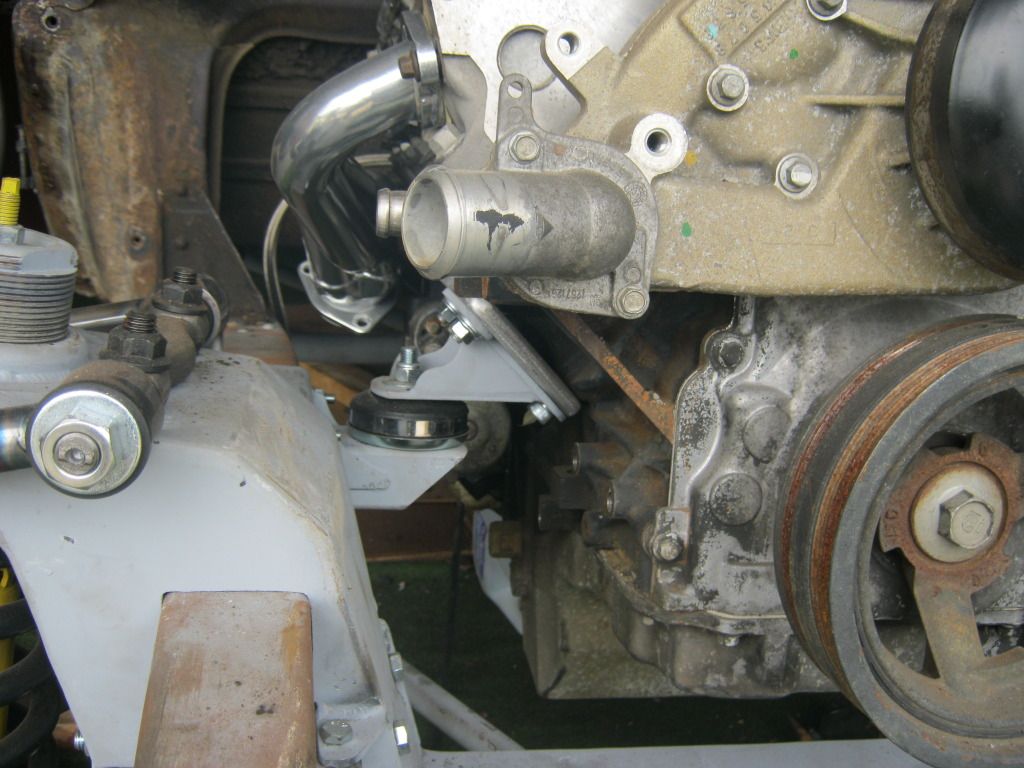
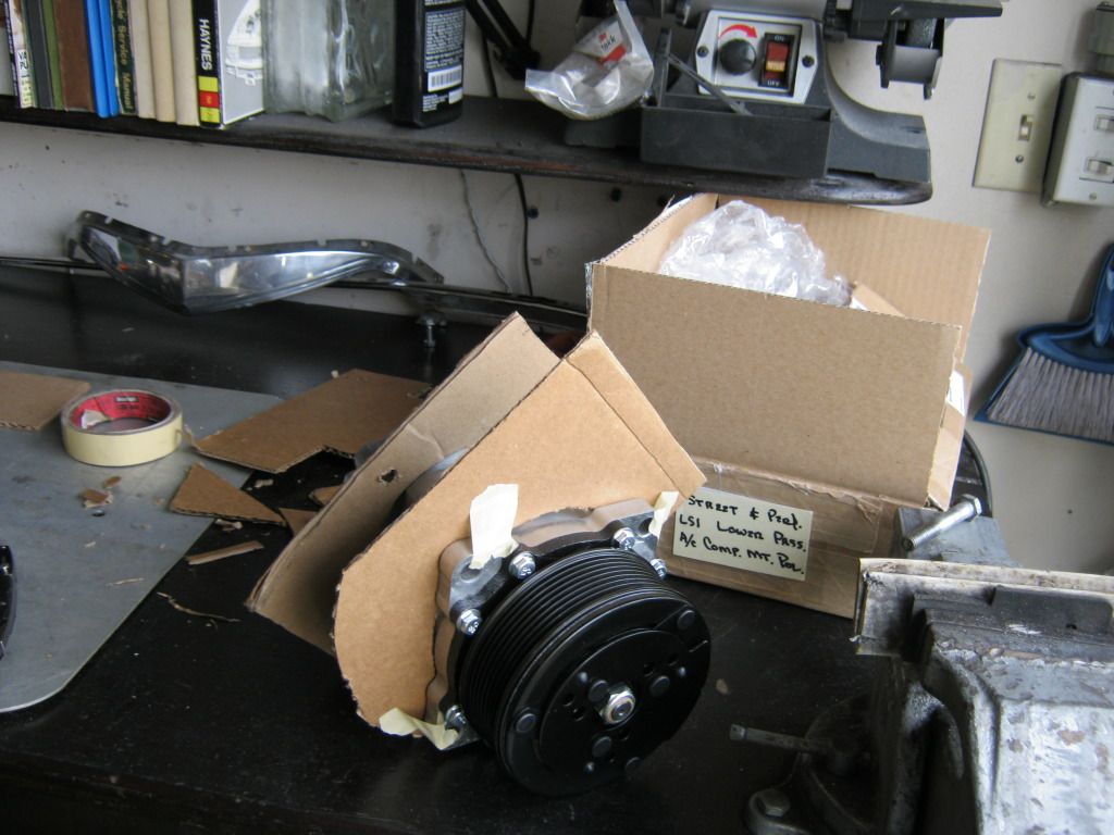
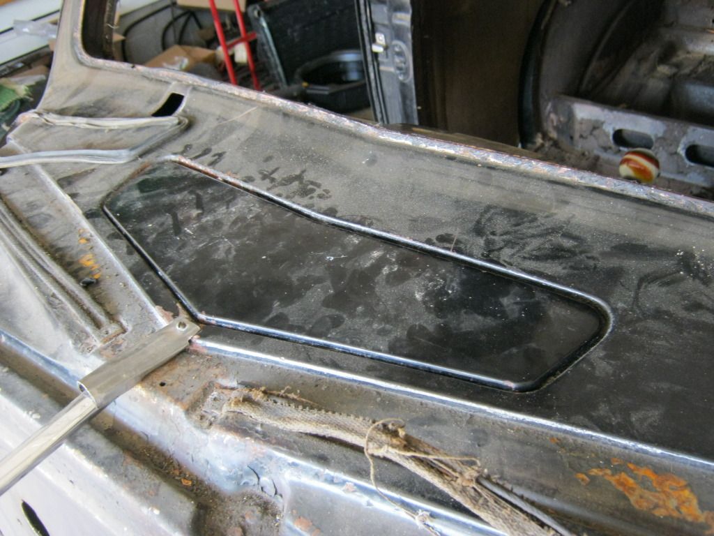
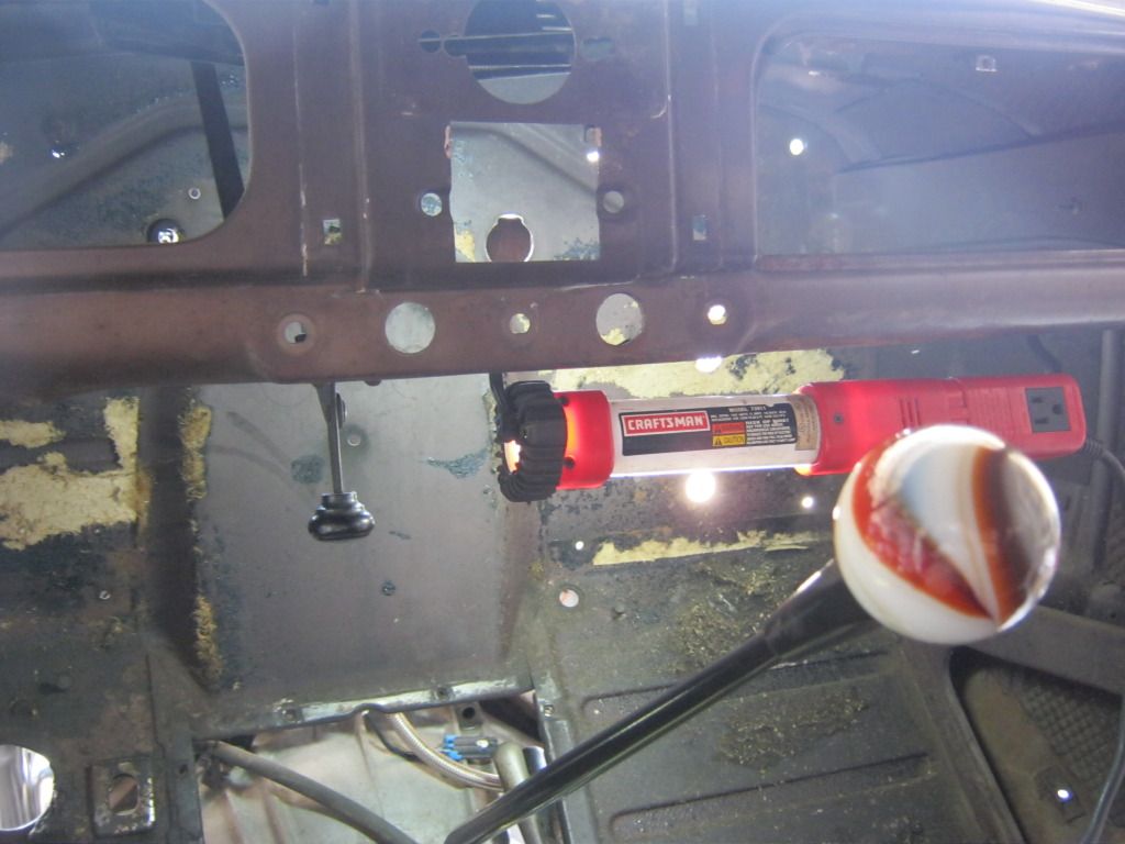
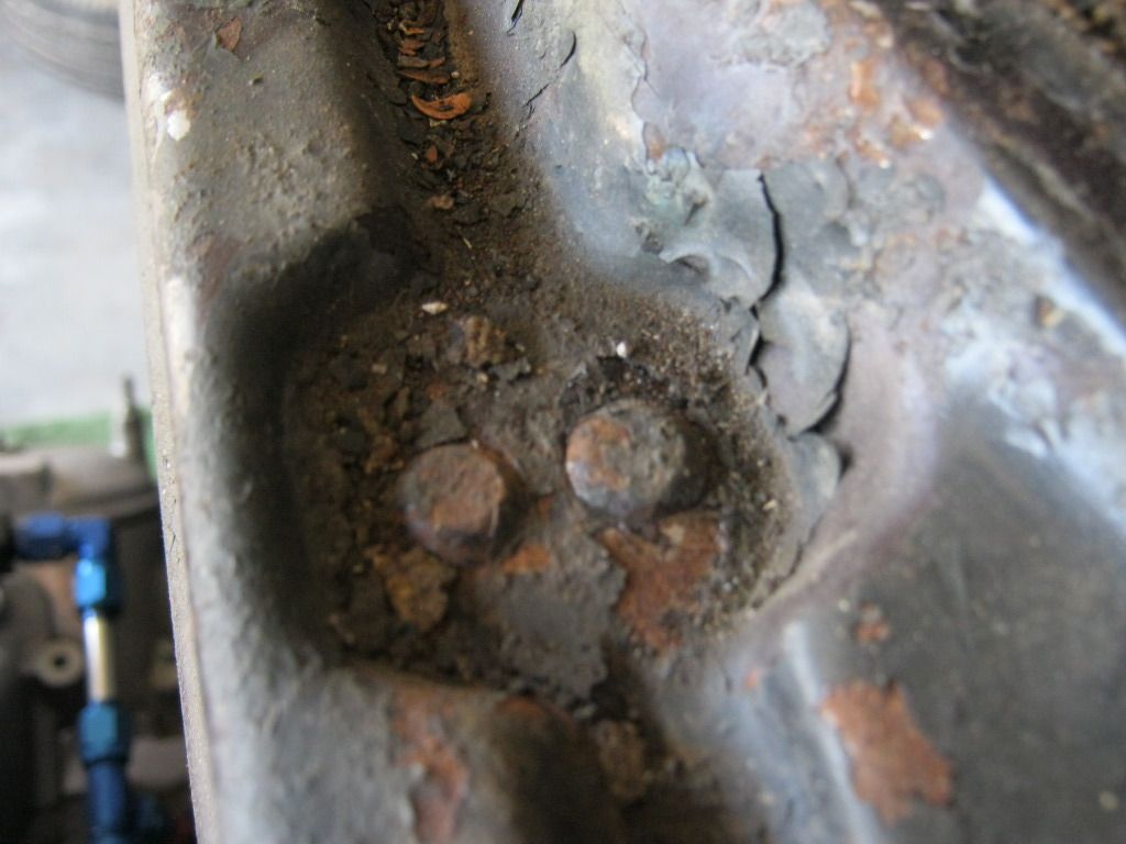
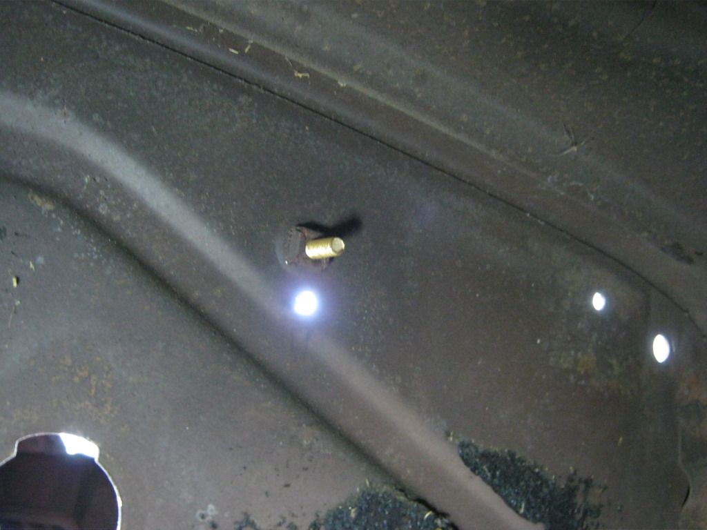
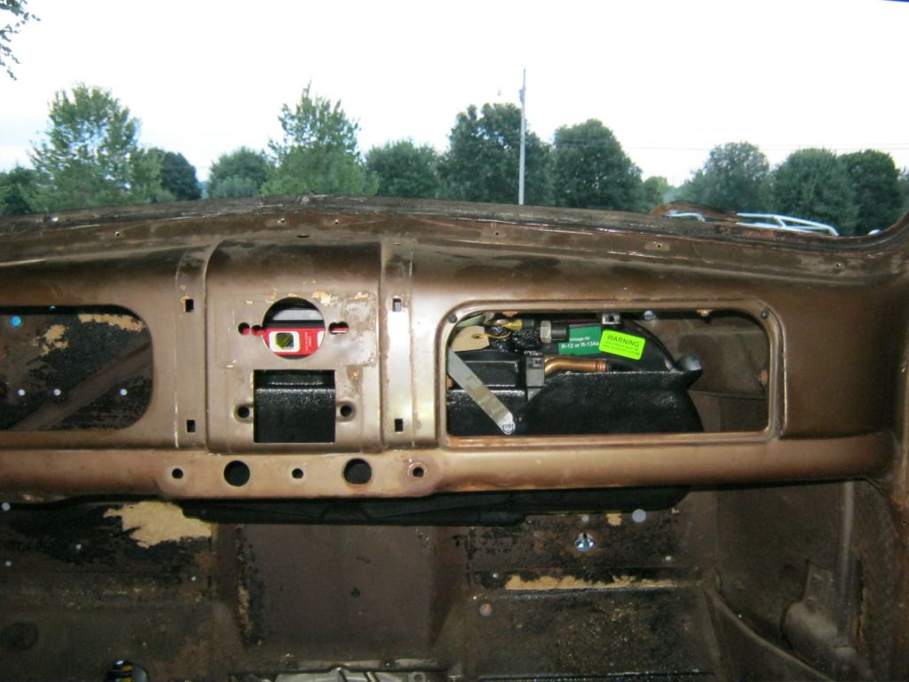
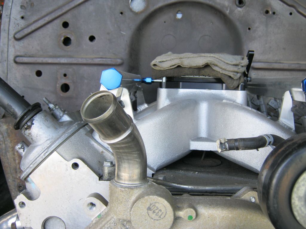
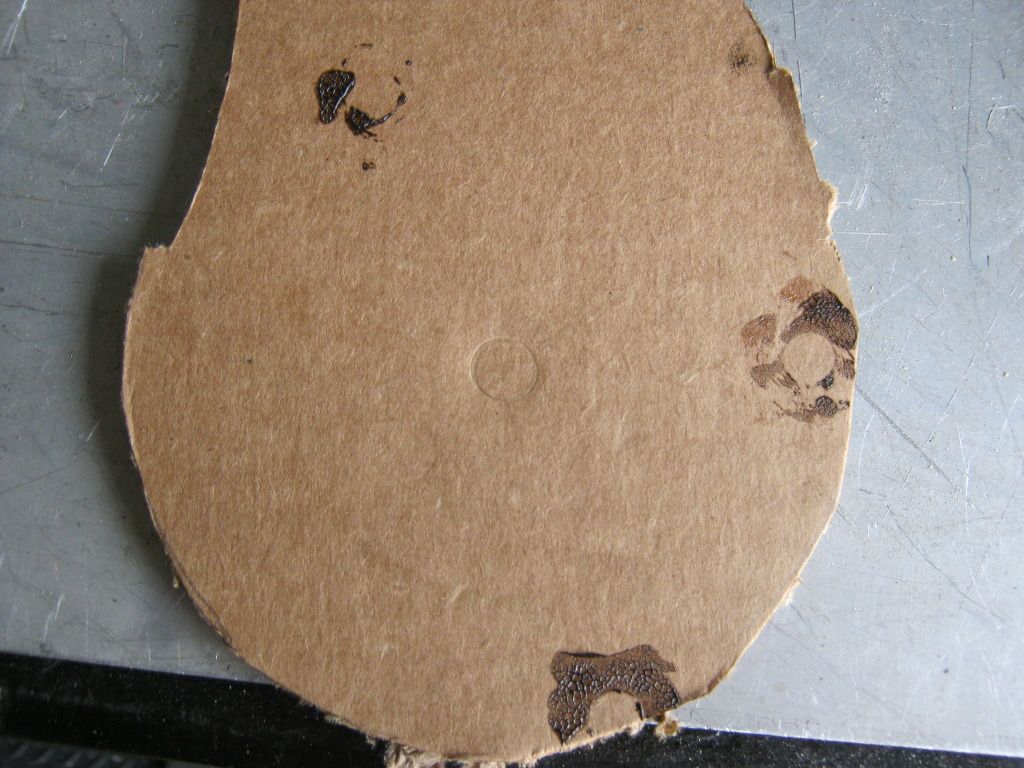
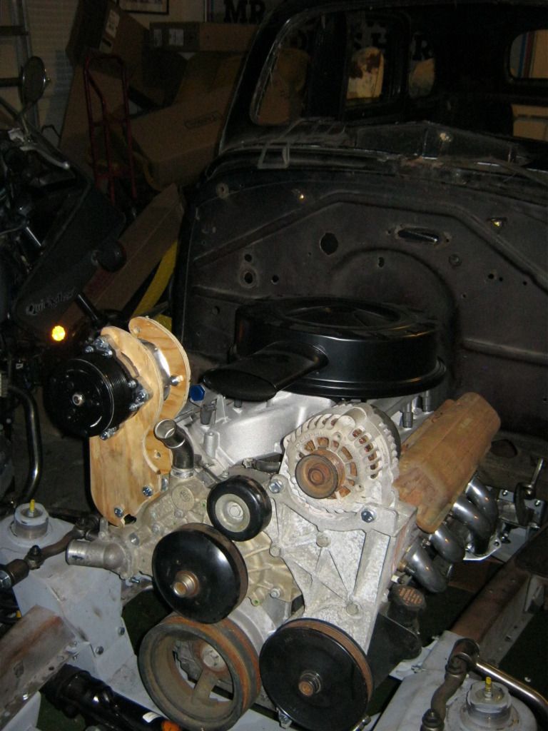
 A big issue that I was going to have to face was whether I would be able to move the water neck in the water pump.  The pumps for the Camaros and Corvettes exit in the flat spot just below the water neck pictured below, in the flat spot where there is nothing, and sticks straight out.  On the truck it goes straight up and at an angle, as pictures.  This was already going to be inconvenient because my upper radiator hose connection on the radiator is almost straight in front of this water neck so being at an angle would make finding a hose a bit more difficult, but after I had to move the compressor up top it interfered with the bracketry and now I would have to move it, or find another pump.

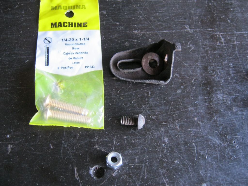
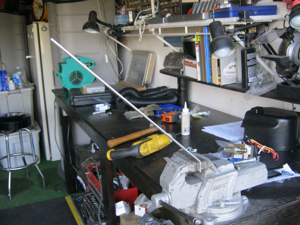
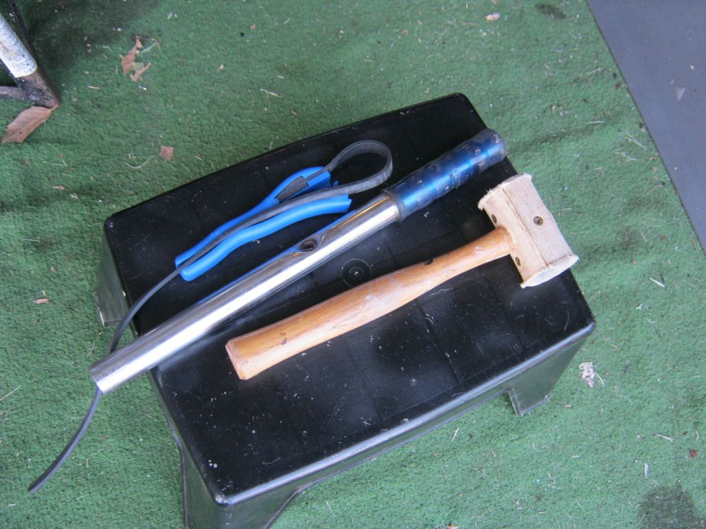
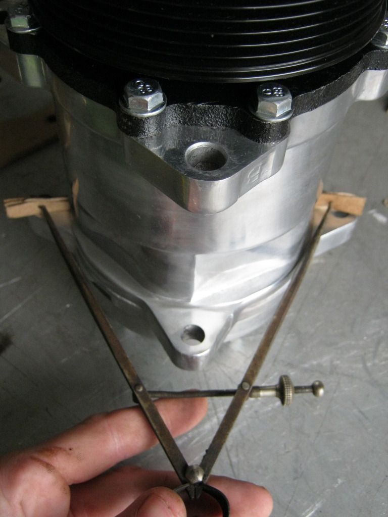
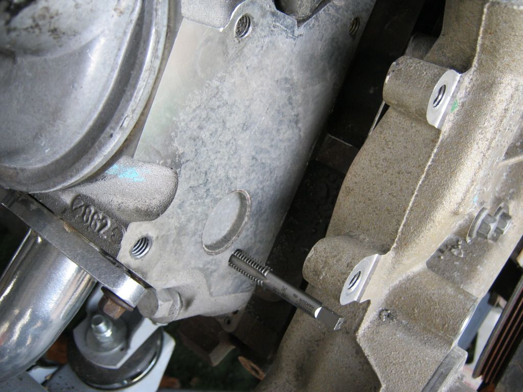
Fortunately, I was able to remove this piece.  It was a small change, but made a very big difference.  I was able to use these tools and get the job accomplished.


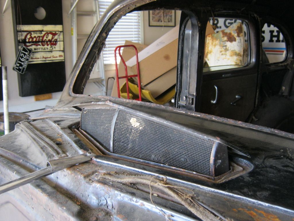
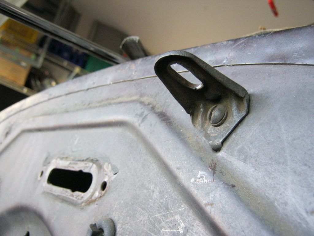
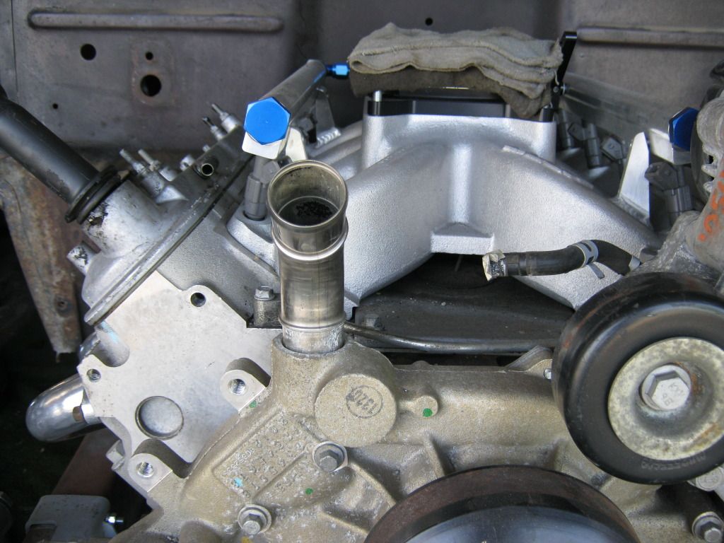
Here is the water neck where it needs to be.  I didn't drive it back in because I'm going to replace this pump with a new one anyway and also I wanted to keep my options open in case something unforeseen happened with the brackets.  I was only testing the removal process on this pump for learning purposes so when it comes time to do the real pump I can hopefully do so without damaging it.  I'll use a sealant on the water neck when it comes time to replace it.


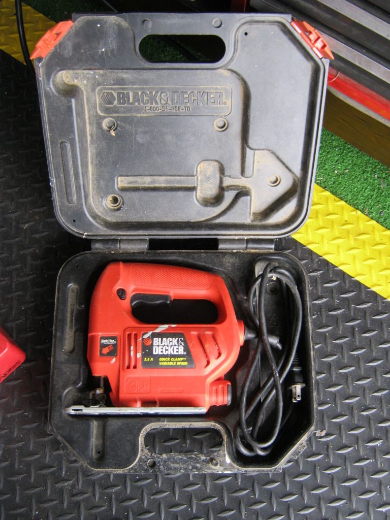
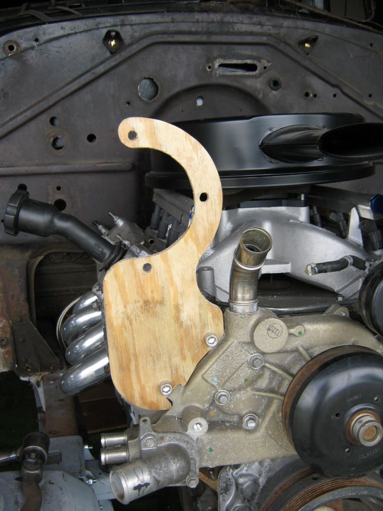
Though I had already gone to the scrapyard and bought a large piece of steel for the bracket templates I opted to make the bracket templates from plywood as others have done.  I know I'll have a use for the steel in the future.  I already had some scrap plywood left over from making my workbench in the garage and the lawnmower shed out back.  This ended up being much, much easier, less time consuming and cheaper when considering all the grinding wheels I would have gone through.  I have also grown to hate the dust that's created when using cutting and grinding wheels.  Aside from getting all over everything in the garage it also gets all over your clothes and in your lungs, even when wearing a mask.  Also, wearing ear plugs, a mask, safety goggles and gloves when it's this hot outside is definitely uncomfortable.  My brother-in-law's father, Dave, has always been into woodworking so he let me borrow the appropriate tool for the job, a jigsaw.

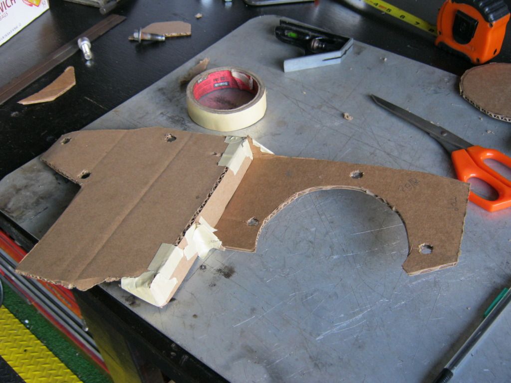
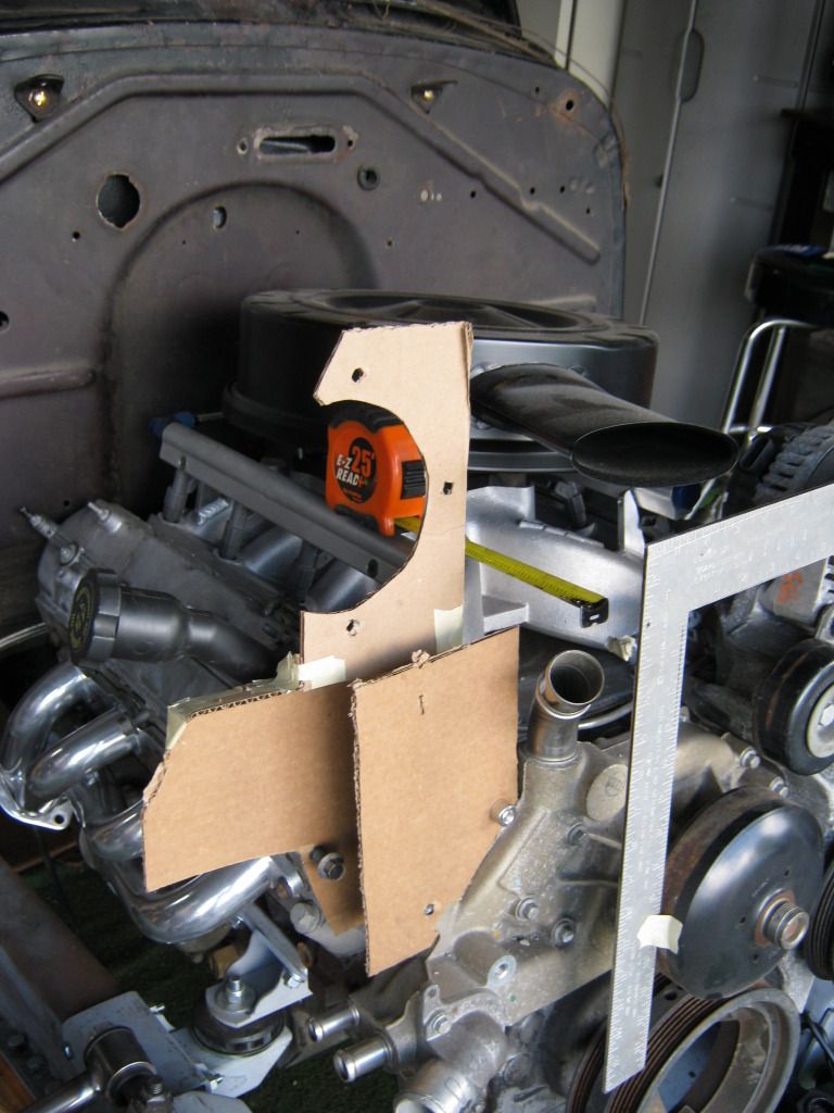
I used the cardboard templates I made earlier, but parts of them were just rough estimates to get spacing right so I had to do some fine tuning to get everything the way I wanted it.  I didn't have a tool that would reach the appropriate areas so I had to stick some cardboard on the end of my tool to get the measurements I was looking for.  The ends of this tool stick outward and is used for measuring the interior distances of objects, thus necessitating the cardboard.


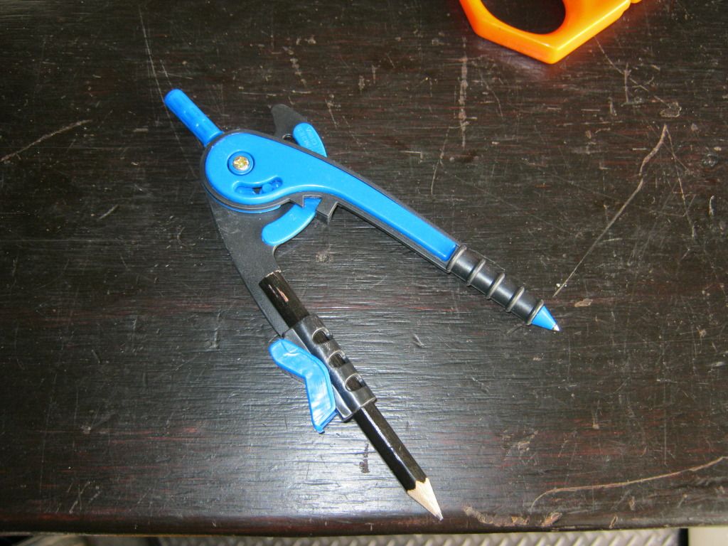
I also couldn't find a single one of my compasses so I had to stop by the store and buy one.  All they had were plastic ones.  I hate the day we live in where nothing is made of metal anymore.  If you weren't careful, this thing would actually bend and distort the pattern.  It also had a "safety" point on it because apparently children today and too stupid to not stab each other with them and then have their parents sue the company.


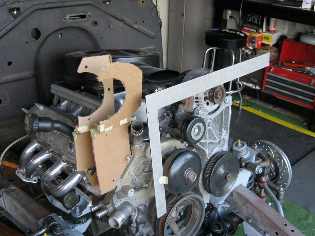
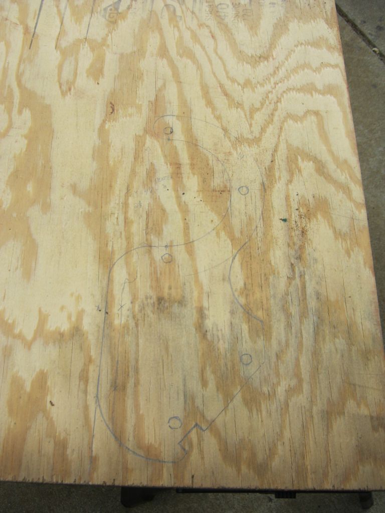
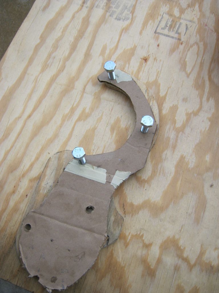
I used the cardboard templates to get rough estimates and then fine tuned those with the compass, using the cardboard for alignment with the placement of the bolt holes.  You can't see them in this picture but wood is nice because you can write measurement notes all over it in pencil. 

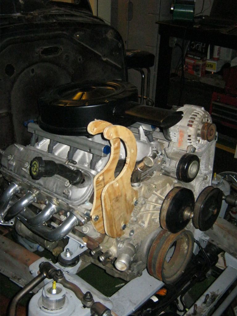
I had never used a jigsaw before, but this thing was great.  I used two separate blades, one for the straighter areas and one for the sharper turns.  It would have taken a million cuts with a million angles and endless grinding to get a piece of metal into this shape with the tools I have available.  This was an infinitely better way to do it.


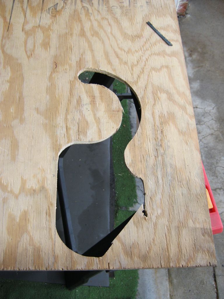
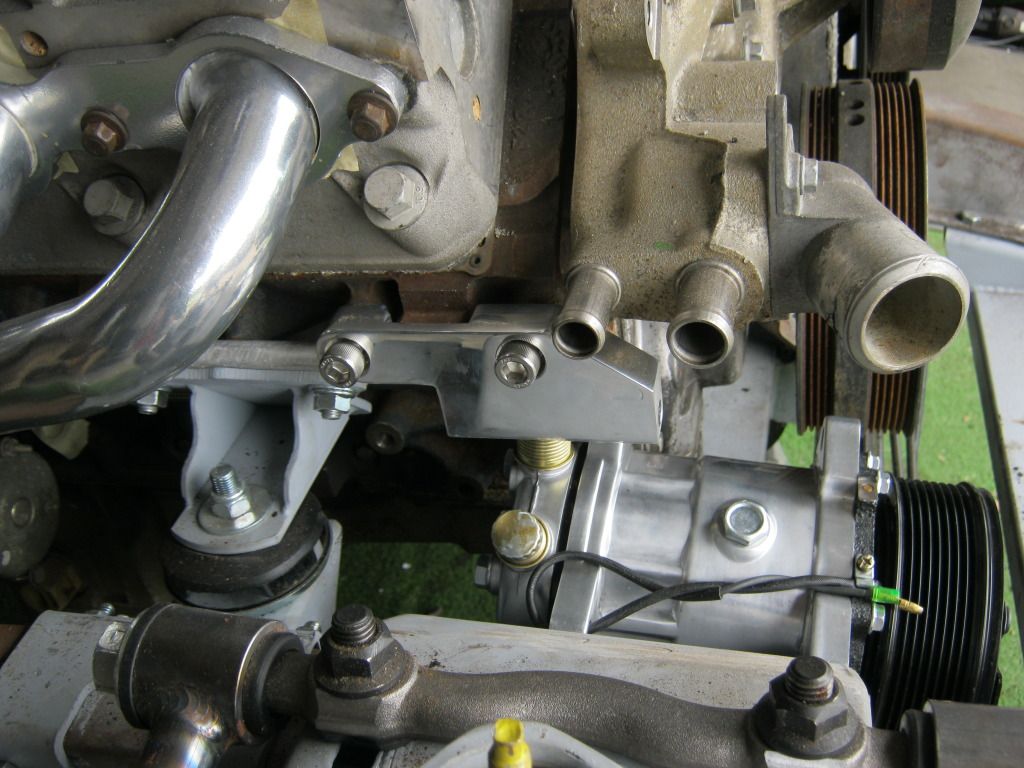
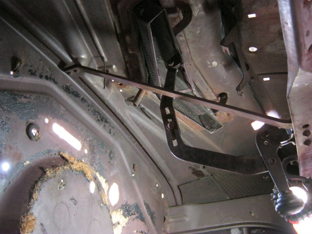
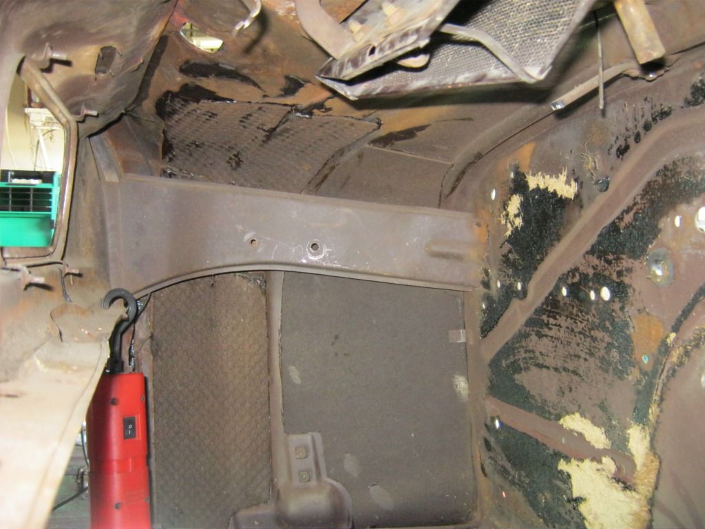
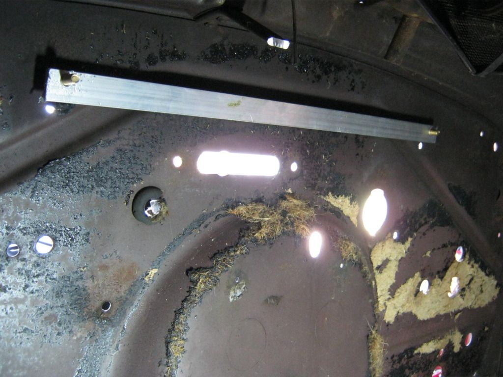
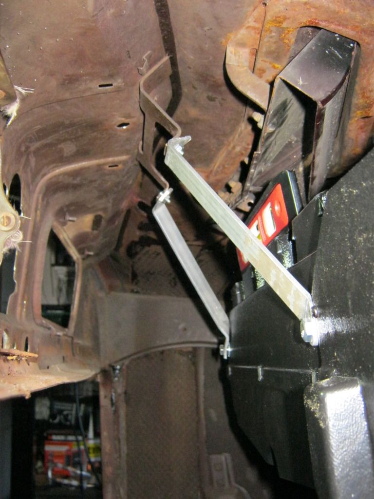
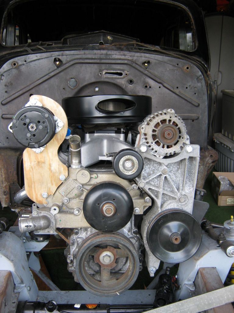
 Here's the first one bolted up.


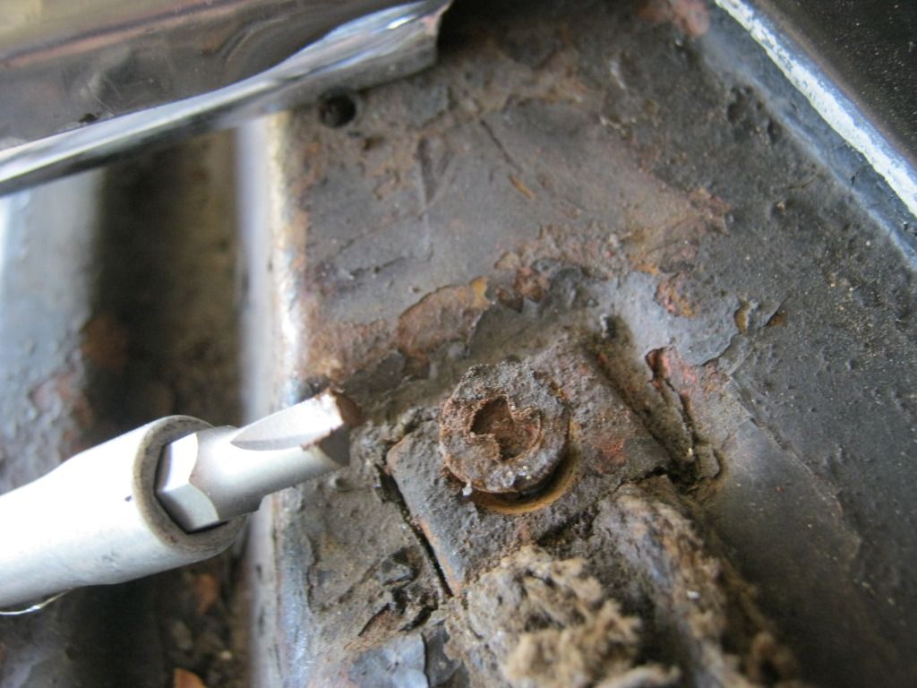
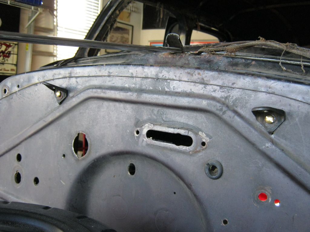
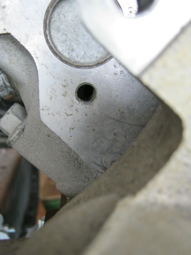
Dirt dobbers had gotten into a few of the bolt holes and I couldn't get bolts to thread into them.  A couple of them were actually covered completely over.  I used a small sharp tool to clean them out the best I could and then had to buy a 10-1.50 metric tap to chase the threads because all of my tap and dies are standard.


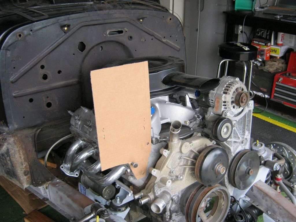
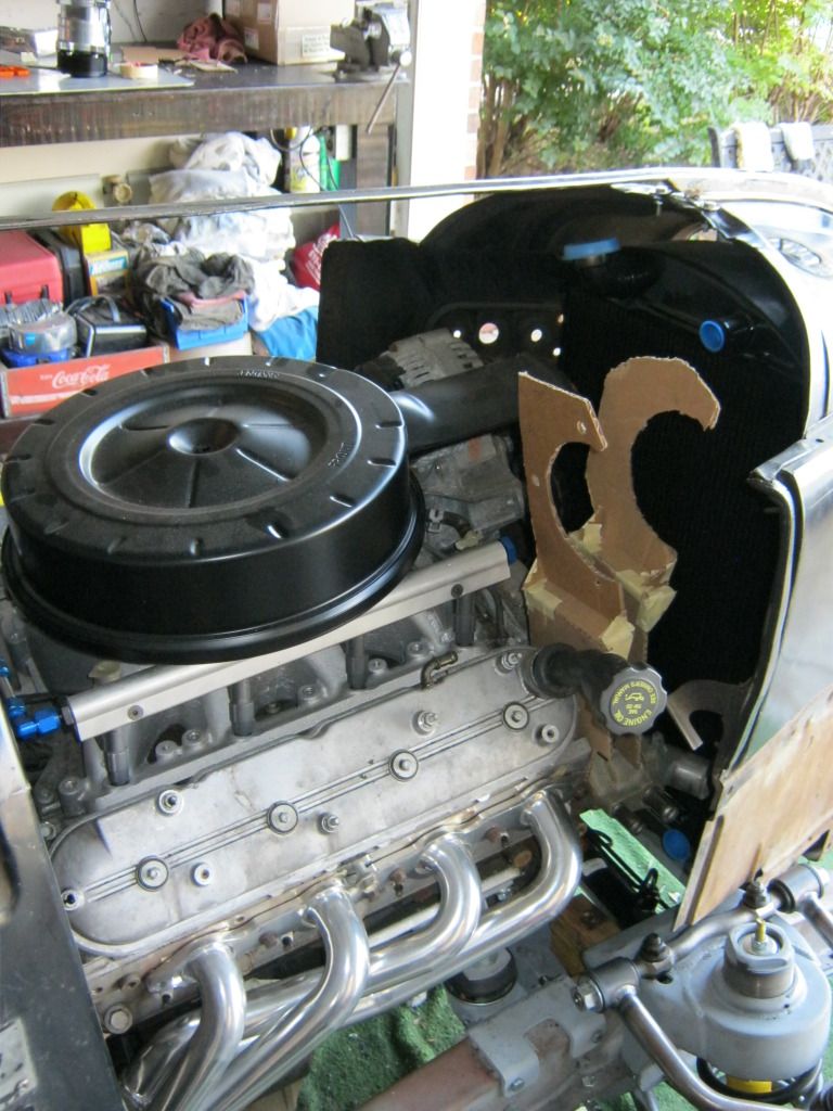
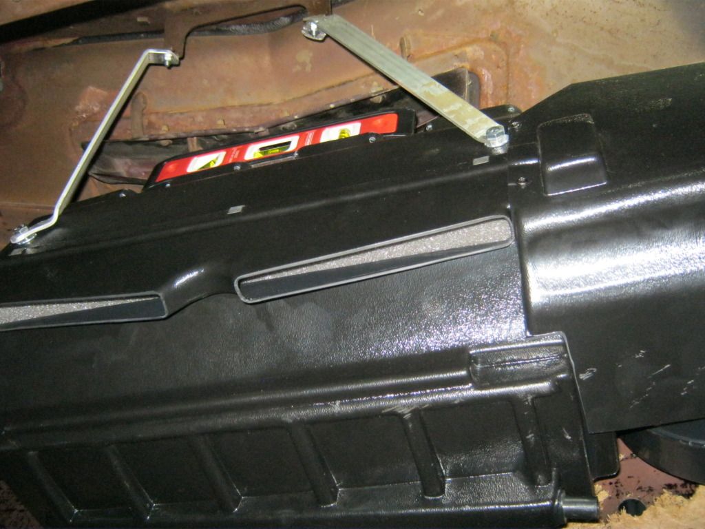
I lowered the final height of the compressor several inches compared to the initial design I had made with cardboard because it was far too high.  Though it would have fit under the hood, it would have been close.  When I took the few inches out of the height something apparently went wrong and my rear bracket holes no longer lined up so I had to mark them again.  There may be a smarter way to do this but the only way I could think of at the time was to put some black grease around the holes and then push the cardboard up against it.


Then it was on to making the outline for the 2nd bracket.  I used the top part of the 1st bracket I made as a template for the top part of the 2nd bracket because I wanted them to look the same.  Surprisingly I found that the bolt holes for the front of the compressor did not have the same spacing as the bolt holes for the rear of the compressor.  They weren't far off, but enough that I couldn't use the same template to mark the hole locations.  


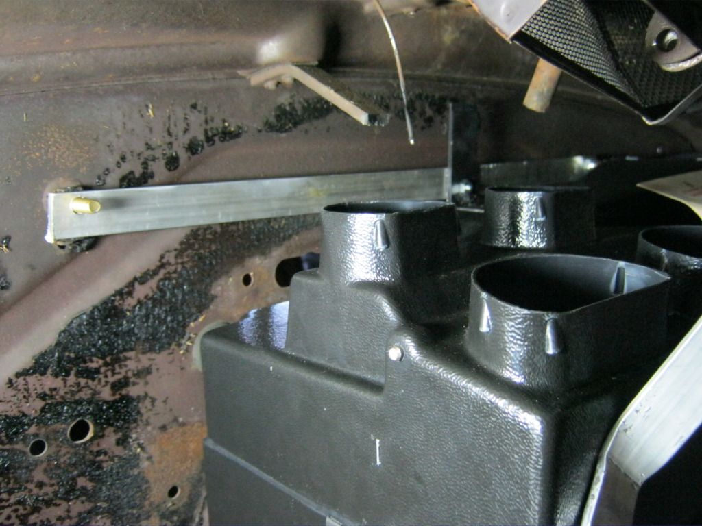
After getting all the holes drilled and the templates cut out I had to do a little fine tuning.  When I put the spacers behind the templates it caused some interference I hadn't accounted for but with a little trimming they fit like they should.


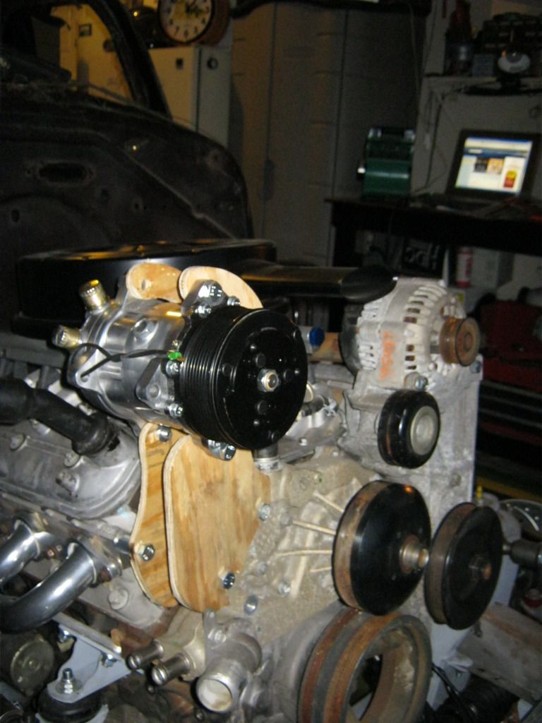
I believe I'm going to raise the compressor 1/2" on the final product.  This will allow room in the future when I make my custom valve cover covers.  I'm going to use old small block Chevrolet valve covers and mount them over the existing valve covers to enhance the overall appearance and make it look more like an old school motor.

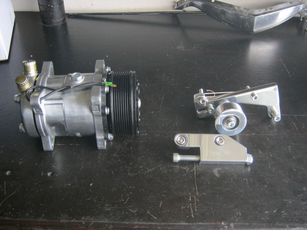
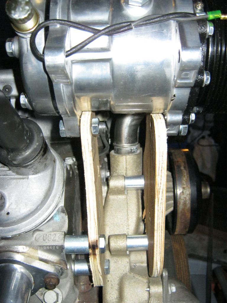
Here are the spacers.  The design isn't completely finished.  I'm going to have one of the bolts go all the way through both brackets for added support and I'll have a long spacer for the bolt to go through.  There are also two spacers missing because the parts store didn't have enough in stock.

Next will be getting the tensioner and idler pulley added.  


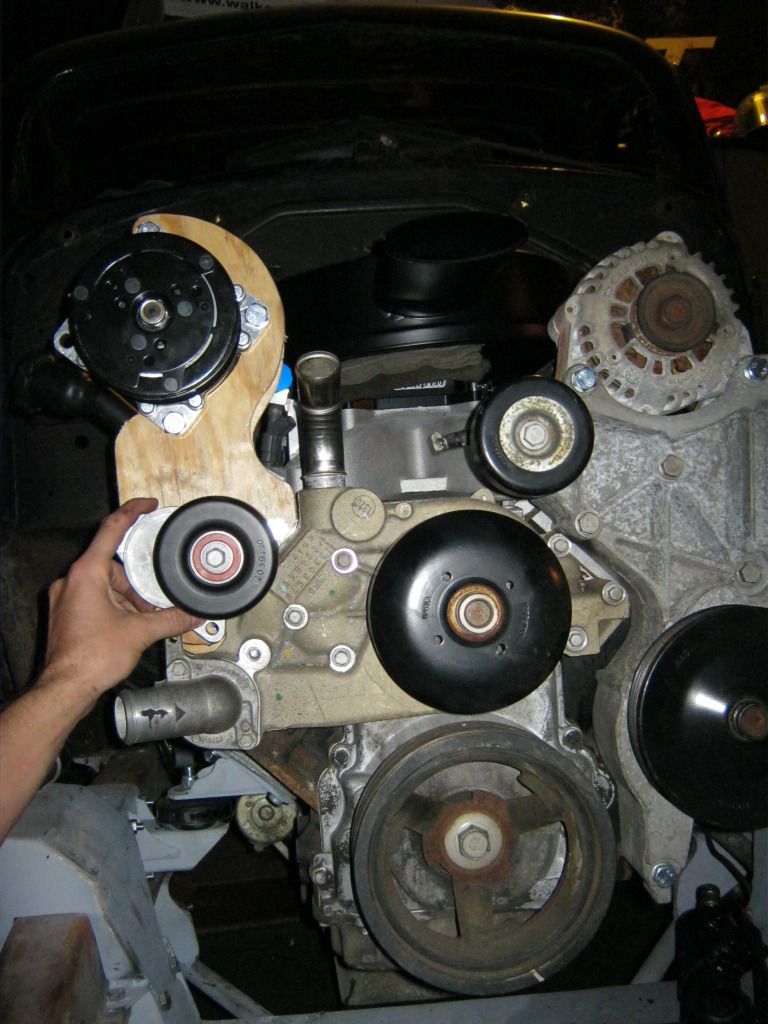
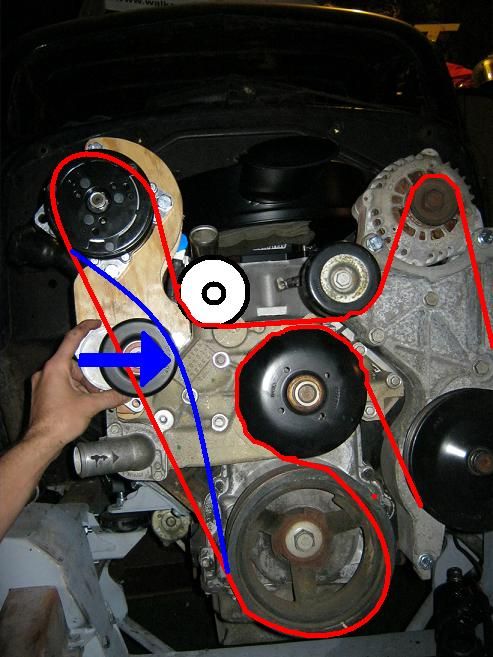
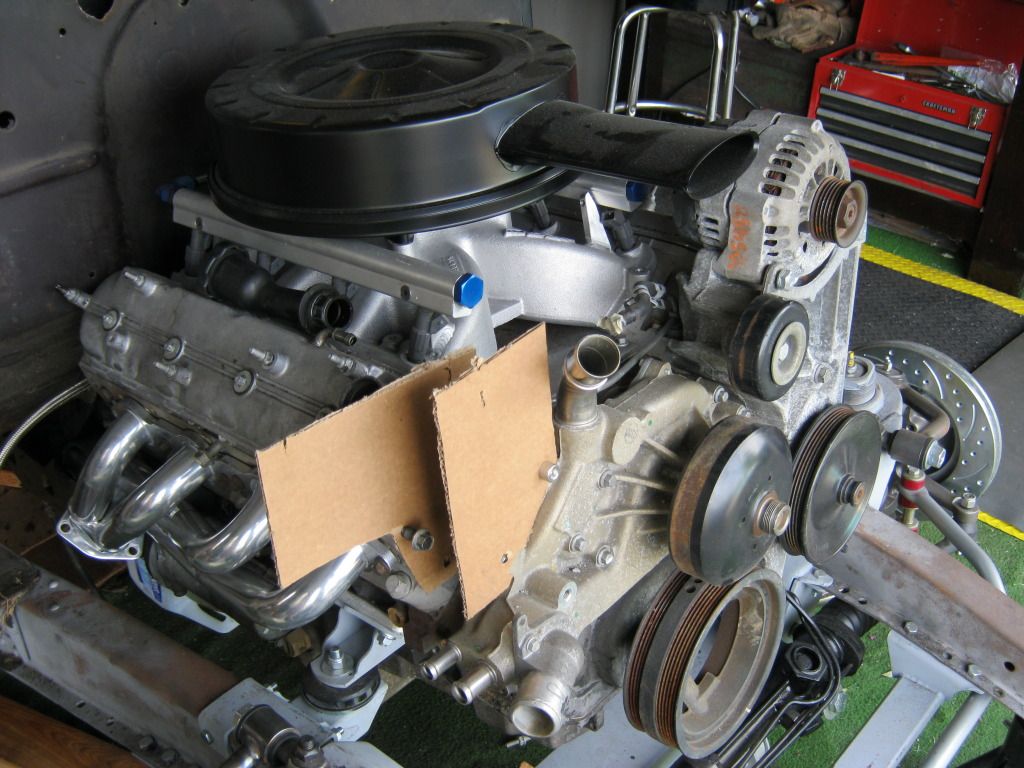
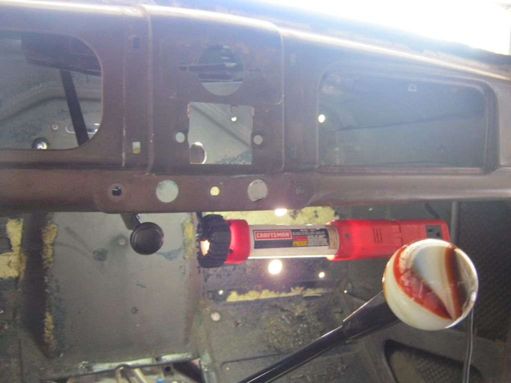
In the end, this is hopefully how the belt will run.  The red line indicates the path of the belt and the blue line indicates how the tensioner will effect the path of the belt.  I used this picture to pose the question of where to mount the tensioner so that it does not cause too much, or too little, tension on the belt.


Tuesday, August 28, 2012

Compressor Bracket's are Expensive

Bill let me borrow an extra compressor mount just to see if my compressor would fit before I bought a mount for myself.  It will not, in fact, fit.  I tried and tried.  A possible blue hue could be seen in my face from trying so hard, but it simply will not fit.

Many independent front suspension kits offered for or fitted to these cars fit in many different ways.  Almost none of them are exactly the same.  Many of the kits offer room to mount the compressor down below on the passenger side where it belongs but the spring top hats from the Chassis Engineering kits are bulky to allow the compressor to fit.  It may physically fit, but in order for it to go it requires turning it in such a way that the outlets for the air conditioner hoses are pressed right up against the block.  Even if that were not a problem there also isn't room for the belt tensioner to fit.

It's a shame to let this much free space go to waste.  Bill and I are both currently looking for a 90 degree swivel water neck so that I can point it straight down.  Street and Performance offer one but like everything else they offer it's very expensive.  If we can't find anyone else that sells one I may end up having to buy one from them.

Here is the compressor not fitting into the location that I so much wish it would.  This means I'm going to have to mount it up top.  At least a benefit to this is that it will no longer be under the thermostat housing and heater hoses in case of leaks.  It will also be up top away from grease and road grime.  Should I ever need to replace it, or I should rather say when I need to replace it, it should be easier being located up top. 

Because my horizontal movement is limited by the narrow front of the '37 I don't have much right to left movement for my engine accessories.  Because of this, none of the kits I have found will fit.  They all put the compressor too far out from the engine and it hits the side of the hood/grille shell.  There is at least one company that makes an entire front mounting kit for the accessories, which is essentially just a machined piece of metal that mounts the power steering pump, alternator and compressor but it costs $2,500, which is absolutely ridiculous.  I paid half that for the entire engine and transmission.  So because of this I was resigned to begin making my own compressor brackets.  I'm really not crazy about making my own brackets here because the alignment of the compressor must be precise or it will throw belts.  Also, I have to find a tensioner and find a way to mount it properly within the belt system to give just the right amount of tension or the belt can slip or be thrown.  I have no idea about how any of that works so I would much prefer to just buy a kit already made but that seems to be a cost prohibitive luxury for this part of the project, and so I began making my own brackets; First out of cardboard.

I began by getting the circumference of the compressor body and making some 3 point C-brackets.

And then some brackets that will bolt to the block and water pump.


After lots of measuring and holding the compressor up with a measuring tape, a feat my arms quickly grew tired of, I got a pretty close estimate to the spacing I'll need.  I added a 1" horizontal piece in cardboard to find my spacing but on the actual mount I may make the entire piece flat and use round spacers against the block to move the bracket out to where I need it.  This would be stronger and more simple, if room will allow.

I had to make sure the pulley on the compressor would line up with the pulleys on the engine.  It can be deceiving to try to eyeball it because the engine is set back at an angle from the axis of the car and it will distort your judgement.


Here are both brackets in place.  The spacing between the C-brackets will need to be 3 1/4".  I'll also find a way to mount a tensioner below the compressor, near the 5 o'clock position, but before I do that I'll have to find out how to mount a tensioner.

The grille shell assembly had to go on and off a couple of times to make sure the fitment was right.

Monday, August 27, 2012

A Breath of Fresh Vintage Air

The Vintage Air components were part of the order we picked up from Bill and because so much is dependent on the location of the under dash unit I decided to tackle that first.  I have been dreading this since I knew we were going to build this car, but it actually wasn't that bad.  The worst part is that so many things will have to be located under the dash that it's hard to visualize it all without just starting somewhere and I'm afraid I'm doing things now that later I'll wish I had done differently.

Here is everything that came in the Vintage Air box.


I looked through the parts to make sure everything was there and noticed that one of the relays was broken before I took it out of the bag.  One of the reasons I went with Vintage Air is that much of what I read praises their customer support.  I called Vintage Air and they said they would ship out a new relay free of charge.


I installed the cowl vent so I would know how to place the under dash unit.


Here it is from under the dash.  This simple mechanism is actually very ingenious in the way it functions.  It has a couple of pivot points but also had a separate arm that rotates and uses a spring loaded ball to give the vent several options of how far you can open it and it will stay.  Because of the design the last part of closing the arm causes the geometry of the arm to change so that the leverage then pulls the lid down tight against the seal.
I had first mistakenly thought this brace was held in place by the screw on top of the cowl that holds the cowl seal down.  I later realized there were two rivets that hold this brace in place and because I didn't want to remove the rivets it meant that I would have to cut the brace, possibly to weld it back in a different location.

This is the position the handle stays when the vent is closed

And this is the position when it is open

I love these vents.  I think they're one of the greatest functional design elements on the car.  Dad has a '61 Corvette that has one of these vents and it does wonders for cooling down the lower part of the car when you would prefer to have fresh air come into the car.  I understand that these are often times rusted out, as well as the tube that drains the water from the area, however this one is in great shape.

Here is the screw up top that I first thought held the brace in.  I had to buy this special insert that goes into the nut driver to remove it.  It wasn't a loss, though, because this screw, and the others like it, will have to be removed anyway.

Here is where the under dash brace was


And now I have ample room to place the air box.


Here are the two rivets that held the brace to the cowl.  Because they are well sealed I do not want to mess with them and cut them out to create a new possible trouble area that could leak in the future.

The directions for mounting the air unit called for drilling holes in the firewall, but the firewall already has enough holes in it so I decided to go a different route.  These mounts are held in the firewall with screws that have nuts welded onto the back of the firewall.


So I went to the hardware store and got longer screws that would give me some thread sticking through the back side.

While I was there I also picked up some steel straps and some extra nuts and bolts to mount everything with.  I also picked up the extra screws that were supposed to, but did not, come in with the kit.


With the longer screws installed, this is what I had under the firewall


Which then, after some measuring, cutting and drilling, allowed me to install this cross brace that I'll use to hang the rear mount for the air box.  I bought two lock nuts but the girl forgot to put one in the bag so now I'm one short.

From the outside it looks the same as it did, except now with shiny brass screws.


And then it came time to bend and measure and bend and fit and bend and fit and bend and fit and mark and drill some holes and then bend and fit and bend and fit until finally the driver side mount looked like this

I checked again to make sure the car is level so I would know the level was correct.  Not too bad.

And then onto the passenger side, with some more bending and measuring and drilling and bending and bending until this happened.  After I got the final fitment I took the braces off and rounded off the corners and made sure the right side fit when the blower motor cover was put on.

Here's the finished product


And a shot of the brace in the rear


I was pretty happy with how far up I was able to get the unit to go without hitting the cowl vent.  It's much less visible than I had anticipated.  I just hope I won't have to end up moving it down when I start fitting other things up under the dash.