Sunday, March 31, 2019

Condenser Deflectors

I put four new halogen headlights in and then it was finally time to tackle a project I've been anticipating for months now, the air foils to prevent air from flowing around the condenser and radiator.  I had anticipated that this project would be very difficult and had been really dreading it.  The car has been running steady between 200 and 206 degrees, but it's never been over 70 degrees outside.  It's very possible that it wouldn't need the air deflectors, but the summers here can get very hot and the humidity is almost always very high at that time.  I suspect the air conditioner will need all the help it can get on those dog days of summer.  I've never really cared for the original design of the grill on the '78 Caprices.  Maybe one day I'll make a new design that looks like it could have been OEM.


This was the gap on the driver side.  Because of the angle of the picture the gap is a bit larger than it appears in the picture.  Also, the mounting surfaces here will be perpendicular, requiring a right angle in the air foil.

I had anticipated the passenger side was going to be much more difficult because of the air conditioning lines and mounting surfaces, but after some test fitting I found that this side was the easiest, only requiring a single, flat piece of steel with no bends.

I started on the passenger side with some cardboard.

I made the bends, measurements and cuts.

I got this quarter panel to a new Suburban several months ago from the scrap bin at a local body shop.  I picked it up specifically for this project and I'll be glad to finally get this thing out of my driveway.  I transferred the cardboard to the sheet metal.  I was really surprised how thin the metal is on newer vehicles. 

I made the necessary bends and cuts to the metal.  Watching some videos online have helped me with some techniques to get better at getting the shapes I need.

After a lot of test fitting on again and off again I finally got it to fit into place.

It was at this point I realized I had tackled the piece completely wrong and after some thought realized to do it right I needed to scrap this piece and start completely over.  I had quite a bit of time in this piece up to this point and it was a hard pill to swallow to toss it in the scrap metal pile.  Unfortunately, sometimes you just don't have your head in the right place and you do stupid things that don't make sense.

Fortunately, the new piece, when made correctly, was much less complex than the first piece so it was easier to make.  I fit it into place and then marked and drilled the holes two at a time.  The original setup had a smaller, less effective air foil that mounted in the same location so I reused two of those screws and screw holes.

After creating a cardboard template for the passenger side I followed the same steps to make that piece also, minus the wasting half the day making it the wrong way.

I used an old inner tube from a dump truck tire to make rubber backings for the parts of the foils that would mount to the aluminum condenser.

After the paint dried on the pieces I glued the rubber strips on.

There was very little space on the backside of the core support and getting these pieces mounted was a frustrating effort of dropping screws and then finding them.  They were stainless steel so a magnet woudn't pick them up.

Here is a shot of the passenger side.  They both turned out better than I thought they would, blocking off more of the areas than I had thought they would.  As it turned out both sides were much less complex than I had thought, also.

Almost the entire area on both sides is now blocked, causing the air to be forced through the condenser and radiator.  Below is a picture of the backside on the passenger side.

Saturday, March 23, 2019

A Living Gauge


Today was the first day of mowing for the year, time to get rid of the girls' old beds now that the bunk beds are done and also time to tackle the long awaited fuel gauge problem.  I took the car to Matt (the tuner) late last night and he met me in a parking lot where he reset the fan settings now that I have changed the thermostat.  We set the low speed fans to come on at 206 and go off at 200 and the high speed fans to come on at 215 and off at 207.  This is basically 20 degrees cooler than stock for both the high and the low.  He had tuned five cars that day and showed up in a late 70's Cutlass with an LS swap which had something around 550 horsepower.  I held the laptop while he datalogged.  I hadn't ridden in a G Body in a very long time and I'd forgotten how much smaller they are on the inside than The Caprice.  After leaving Matt I had dropped The Caprice off at the tire shop because I had a bad tire out of balance that came in around 70 mph.  They trued the tires and I picked it up around 10:30 on Saturday and brought it back to start on the fuel gauge issue.

 I first tested the Dakota Digital box to see if maybe when I crimped the wire in the box I missed and made contact on the insulation instead of the wire.  That wasn't the case.  The next connection in the system is where I ran the sender wire from the fuel pump harness over to the engine harness, and I covered that connection in black tape so I skipped it and went to the back to check the ohms.  Zero.  Typically when a gas gauge reads empty it means there is zero resistance in the wire, which means zero Ohms, which means there's usually a short somewhere.  I went to the next connection back, and still nothing.  I also noticed that not only did the sender wire read zero Ohms, it also had continuity with the frame, which meant it was grounding somewhere.  After checking all of the connections the only thing left was to check the tank connection.  I tried to do this by lowering the tank slightly in the front with a floor jack and block of wood, but there just wasn't enough room.  I eventually had to drop the gas tank, which meant I had to remove that filler neck mount that I had just finally finished and got mounted last weekend. The tank was really heavy because it is a 20 gallon tank and I had just filled up before leaving work on Friday; not the optimal time to be messing with the gas tank.

The whole issue with the wiring was very frustrating because I had purchased a Racetronix fuel pump and harness for the fuel pump and sender.  I think I gave an overview of this earlier in the build, but they have the very frustrating policy of providing no instructions with their kit, which requires extensive modifications, and instead require you to join their private web forum to get instructions, which consists of a .pdf article that some guy had written.  Also, if you ever express concern of lack of satisfaction for their product or lack of response on the forum, they ban you from the forum.  On top of this, at the time I bought my kit they had made changes to their kit but this is not mentioned in the articles and the forum tech seemed completely unaware.  I had to stop my work and read through all of the write ups and blog posts I had written on the topic to remember how and why I had to make the changes the way I did.  Also, their "tech" person on the forum had given incorrect answers, but fortunately a member of an Impala forum helped me greatly in figuring it all out the first time around.  After basically relearning this all over again I finally determined that when I had to re-pin the Racetronix bulkhead harness I had accidentally mixed up the locations of the ground and sender wire.  I guess that would explain why the sending unit had a ground problem.  The picture below shows a pen pointing to the harness in question and my elaborate drawing. 

The original problem was made more confusing by the fact that the top side of the connector consists of 4 connectors in a row, while the bottom connectors are arranged in a square.

I swapped the ground wire and the small blue wire, which is for the sender.  I still don't understand why the kit has redundant wires powering the pump.  The thick blue and red wire both splice together in the connector at the bottom of the picture below.  Until this point, I had forgotten how much modification this kit needed and how the customer is basically left to figure it out.  The top of the fuel hanger must be drilled and a screw glued in the hole and the sending unit must have the rivets drilled out so new wires can be soldered on and some wires have to be replaced or cut because the kit has incorrect fittings.  Also, a few wires have to be routed to new locations.


After all of this I made sure I won't forget a very stupid lesson.  On all of the cars I typically work on (pre fuel injection) if you want to test a fuel gauge you can just turn the key on.  On a fuel injected car, if you don't hook the fuel lines up, but you do hook the power wires up and turn the key on, gasoline shoots out of the top of the gas tank.  I turned the key on and thought, "What's that splashing sound?," and then it hit me.

After all of this I modified the Dakota button that I mounted in my ashtray so the ashtray would slide in and out correctly and I also had to modify the button so I could remove it from the mount and turn it over so that the button on top would control the features on the top of the dash and the button on the bottom would control the features on the bottom.

While I was under the car I noticed the pinion seal had been leaking slightly, so I'll need to replace that in the near future.  This has almost concluded the original goal of making the car a daily driver.  Now that the gas gauge works I'll make the 4 hour trek to the bodyshop that is going to repair the rust under the old vinyl top.

Sunday, March 17, 2019

Indiana, Snow, Wires, Warning Lights, Welding


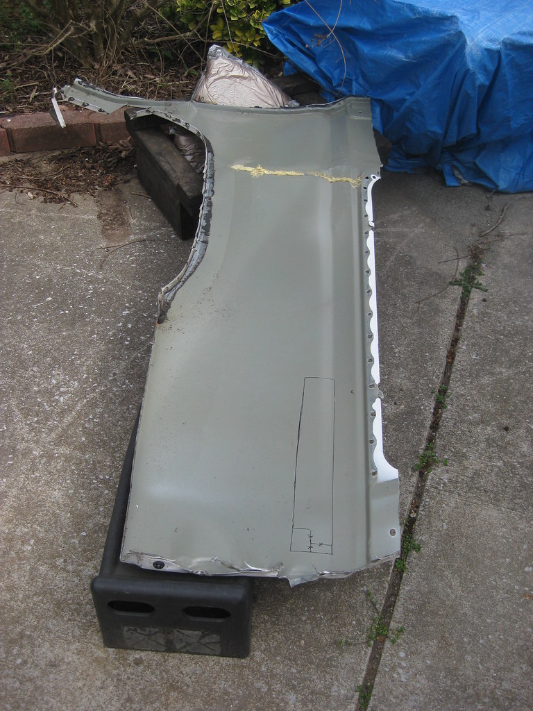
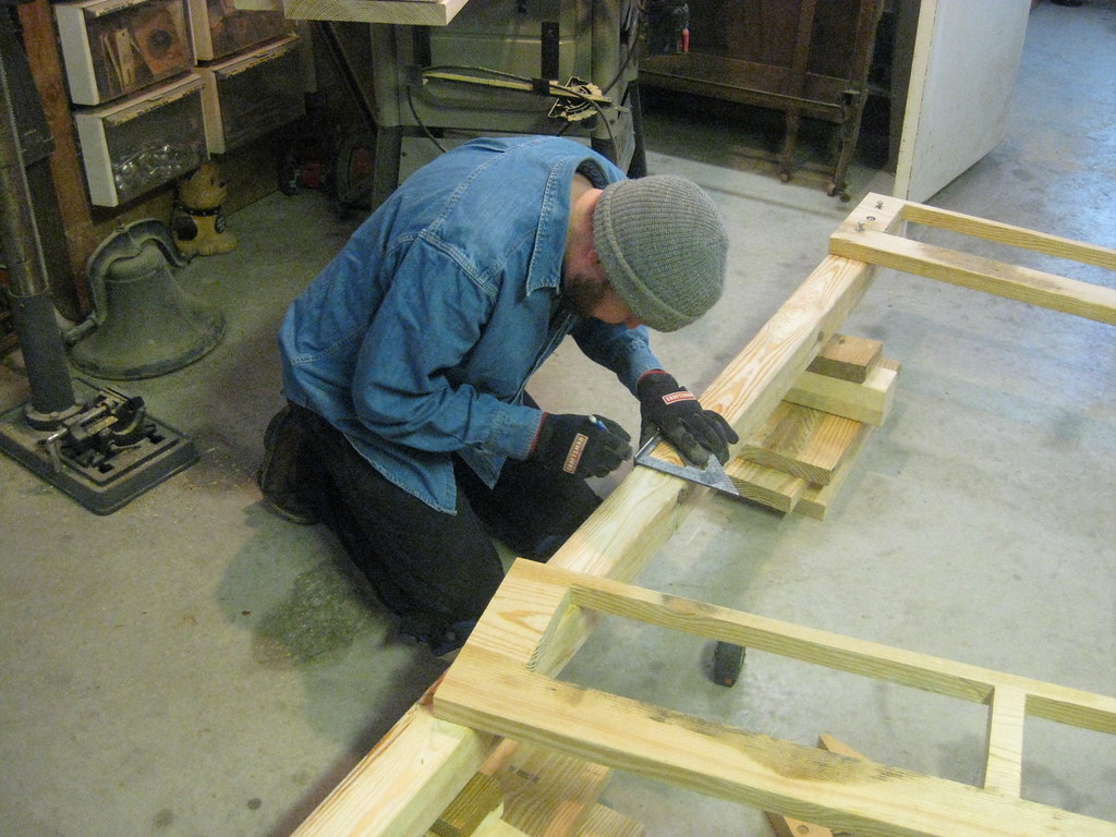
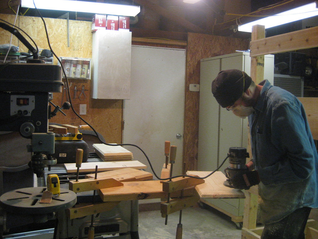
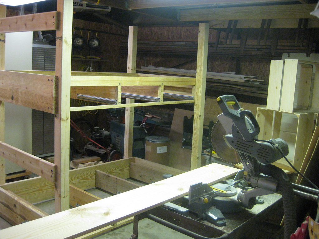
I had to delay progress on the car for quite a while.  I was about to lose accrued vacation time at work so I took a week vacation and built bunk beds for the girls.  I had hoped to begin this project after The Caprice was finished, but several set backs has caused The Caprice project to take longer than I had planned.  My father-in-low let me use his wood shop for the project.  The problem was that he lives 3 1/2 hours away in Indiana.  It was 10 and 12 hours days for over a week and just like all other projects, took longer than I had hoped and I wasn't able to get finished.  After spending about 80 hours that week working on the project I then had to drive back up on the following three weekends to finish the project.  The worst part was the final weekend when I drove back up after letting the paint cure for a week.  It had been raining all week and the ground was so soft even the gravel was sinking in the mud.  I ended up getting stuck in the mud at the shop while trying to load all the pieces in a huge storm.  I had to borrow a chain from a neighbor to pull my Suburban out of the mud and by the end I had to go to a local store and buy all new clothes for the trip home.  Here are some photos of that effort.


Because of my erratic schedule for the last month the following projects were not all worked in order.  I just had to work on different parts when I was able, but in order to make them more coherent I'm going to group the photos of each step together.

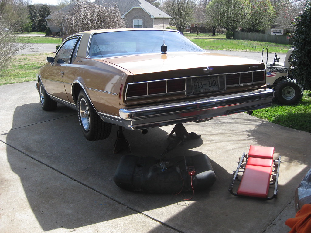
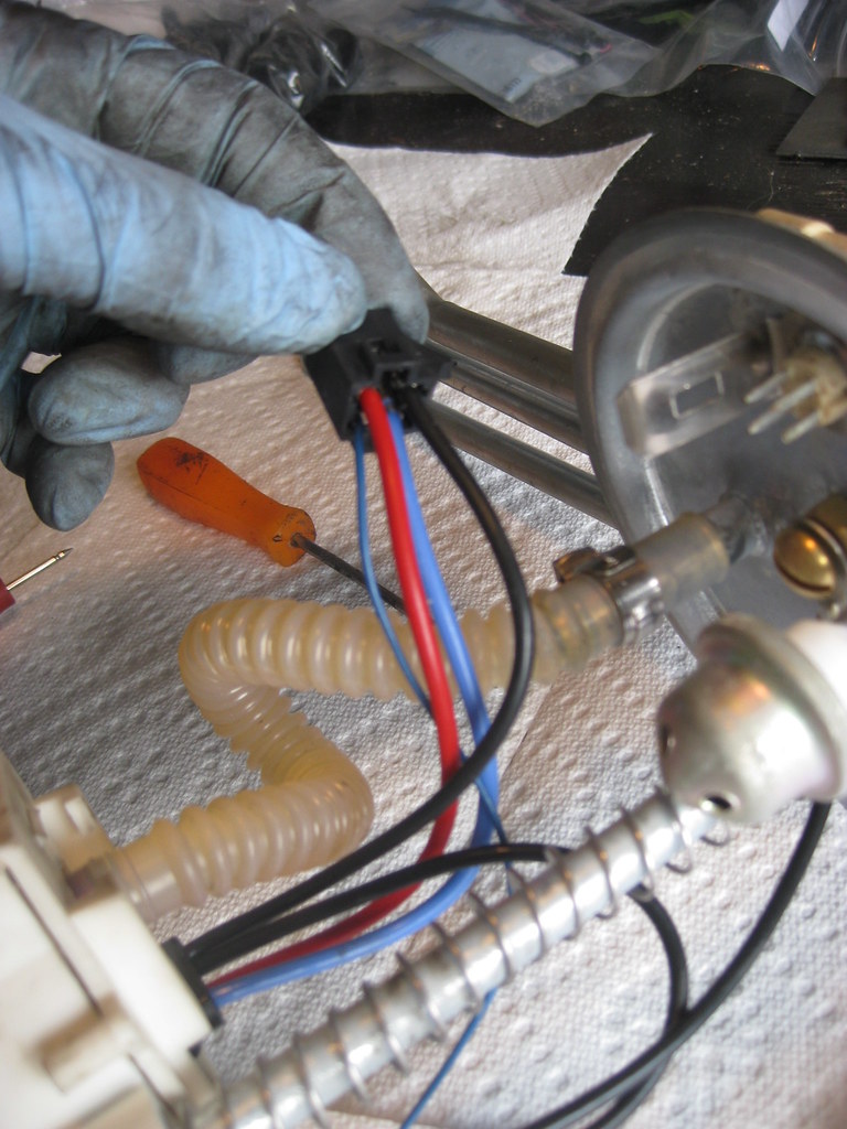
When my tuner drove The Caprice to his shop for the dyno tune he started having issues with the pedal going dead.  We finally decided that the cruise control wires, which I haven't yet hooked up, were shorting out and causing the problem because after moving them out of the way the problem went away.  I picked the car up from his house and drove it home where it sat in the driveway for a few days.  I finally got the back bumper reassembled and back on the car, which ended up taking several days because I had neglected to notice ahead of time that the bumper was held together with two different length bolts and I had trouble finding them.  When I did finish the bumper I decided to drive the car into work for the first time.  The weather was frigid cold, in the 'teens, but I decided to try it out anyway.  When I pulled the car around to the front of the house the pedal went dead and blocked in April's car.  After trying everything I could think of I unplugged the throttle body and plugged it back in and it began working so I thought I had a bad connection at the throttle body.  The next day I warmed the car up, moved all the car seats for the girls over and when we started to take off the pedal was dead again.  As frustrating as it was I was thankful it died in the driveway.  For the next couple of days I used what little time I had to read as much as I could about the problem and having already tested my pedal and tac module decided to remove the harness between them and do a continuity test.  Luckily, I found one connection with no continuity.  I say luckily because had there been no problem with the harness it would have been a lot of work to continue to diagnose the issue.  It turned out there was a cut wire in the harness.

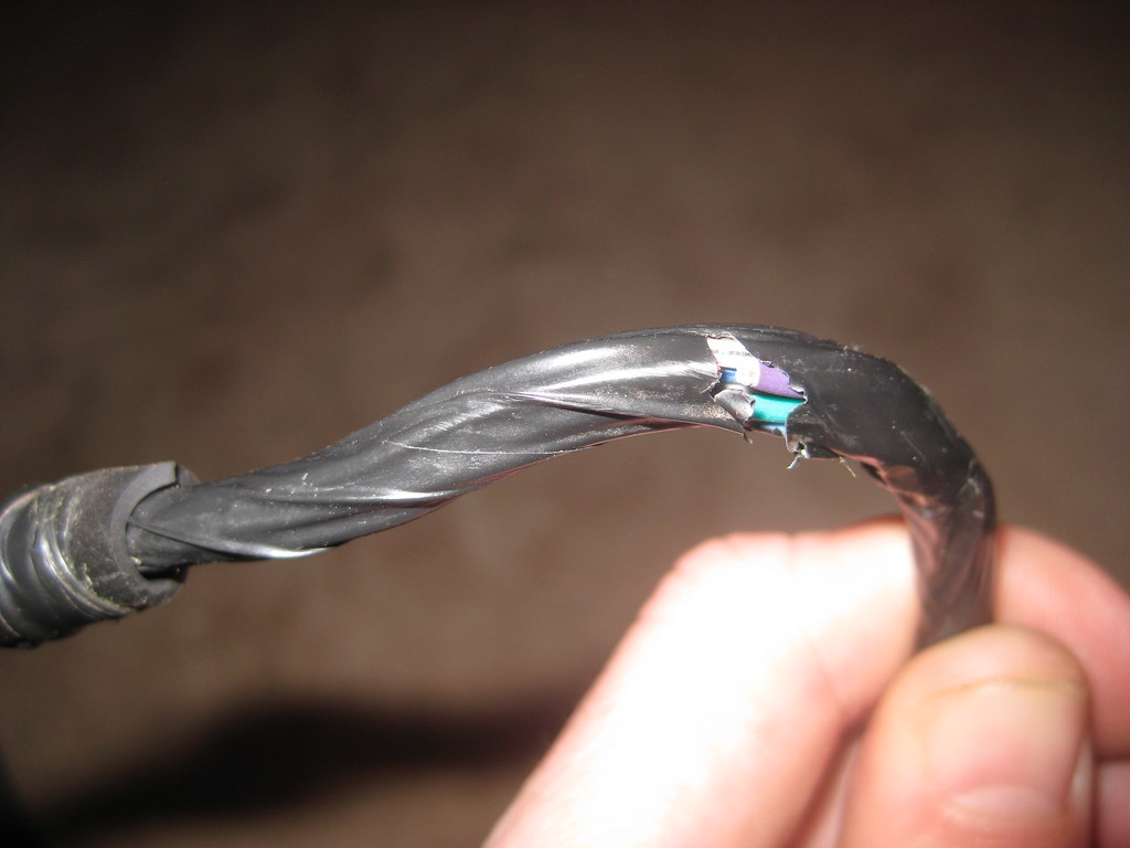
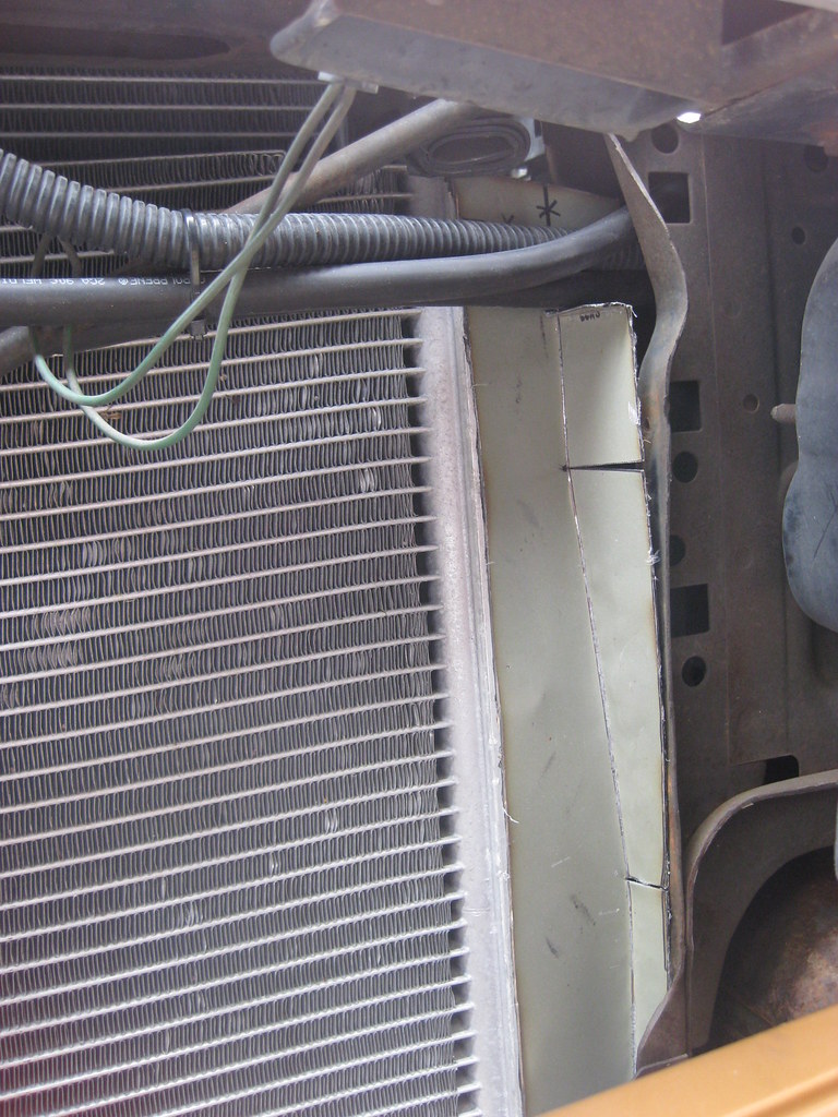
The ironic thing about this harness having a wire cut is this; The tac module was under the hood on the original '04 Avalanche but I mounted the tach module under the dash, much closer to the pedal.  Because of this the harness was much longer than I needed.  I had considered shortening it, but I thought that since it was original I should leave it alone to lessen the chances of me messing it up and causing a problem.  After all of the cutting and soldering and splicing on the entire original harness, the one piece of harness that I didn't end up modifying is the part that caused me trouble.  If I had shortened it to begin with I would have cut out the problem area and probably never have noticed the damaged wire.  I bought all of these pieces from a salvage yard that had separated and cataloged all them, so even though they were all from the same vehicle they had been stored separate.  I suspect that it was during this time that the harness had been damaged.  The below picture is after I removed the factory wire loom and black tape and shows that the one wire was completely cut in half, though no other wires had any signs of damage at all.

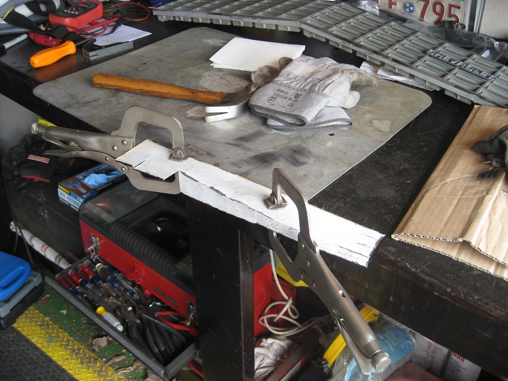
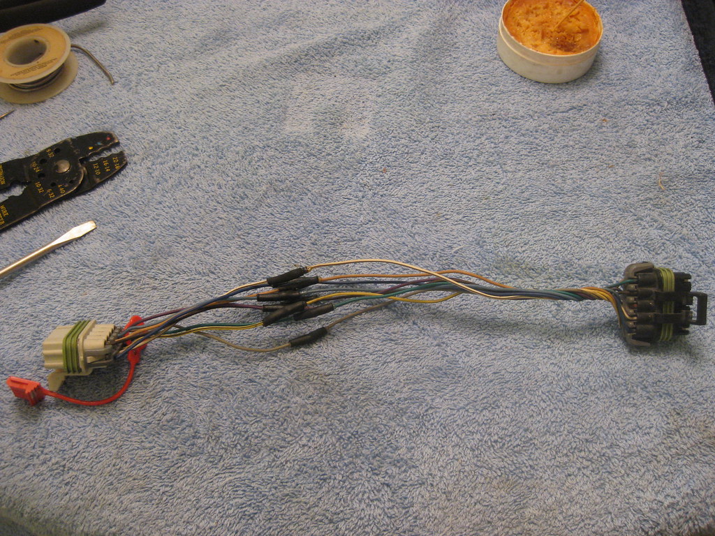
Even though I thought I was done with splicing wires I once again had to reconstruct the solder station, though this time a smaller version.

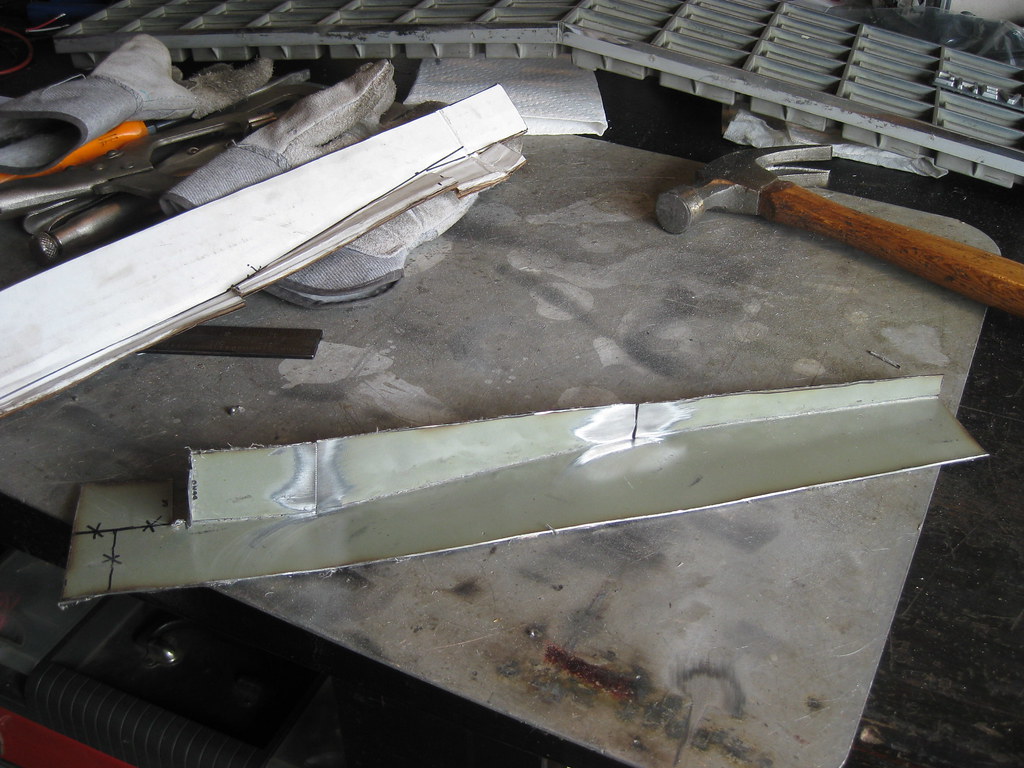
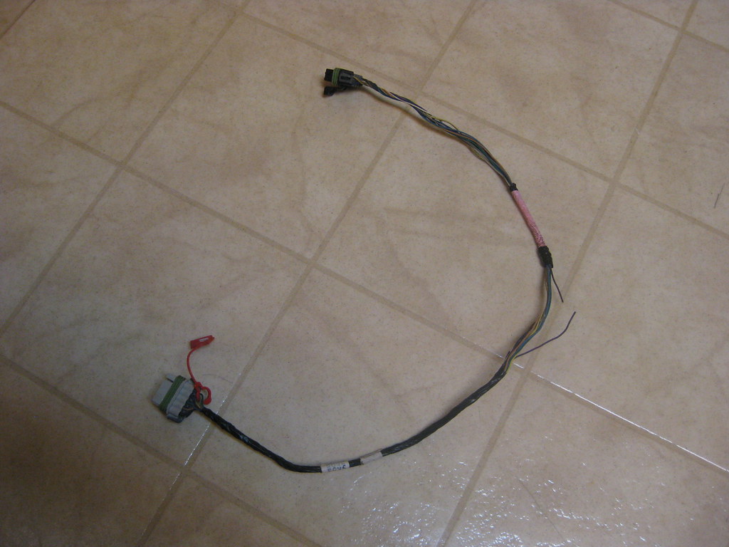
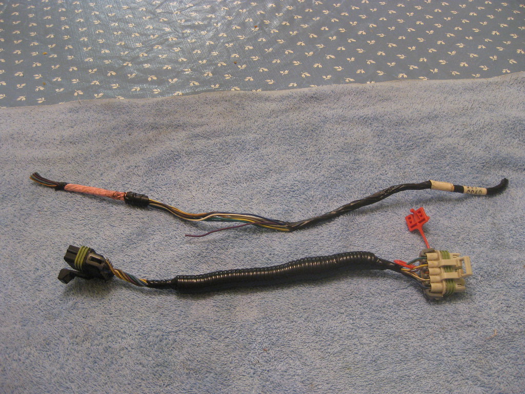
Since I already had to splice one wire I decided to go ahead and shorten the entire harness.

After getting everything back together, the picture below shows how much of the harness I cut out.

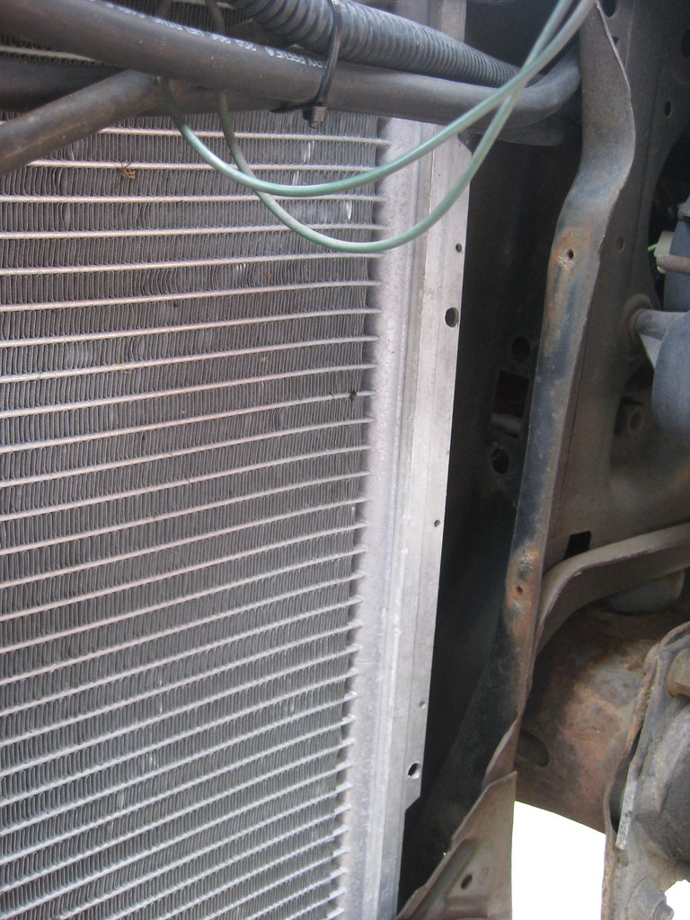
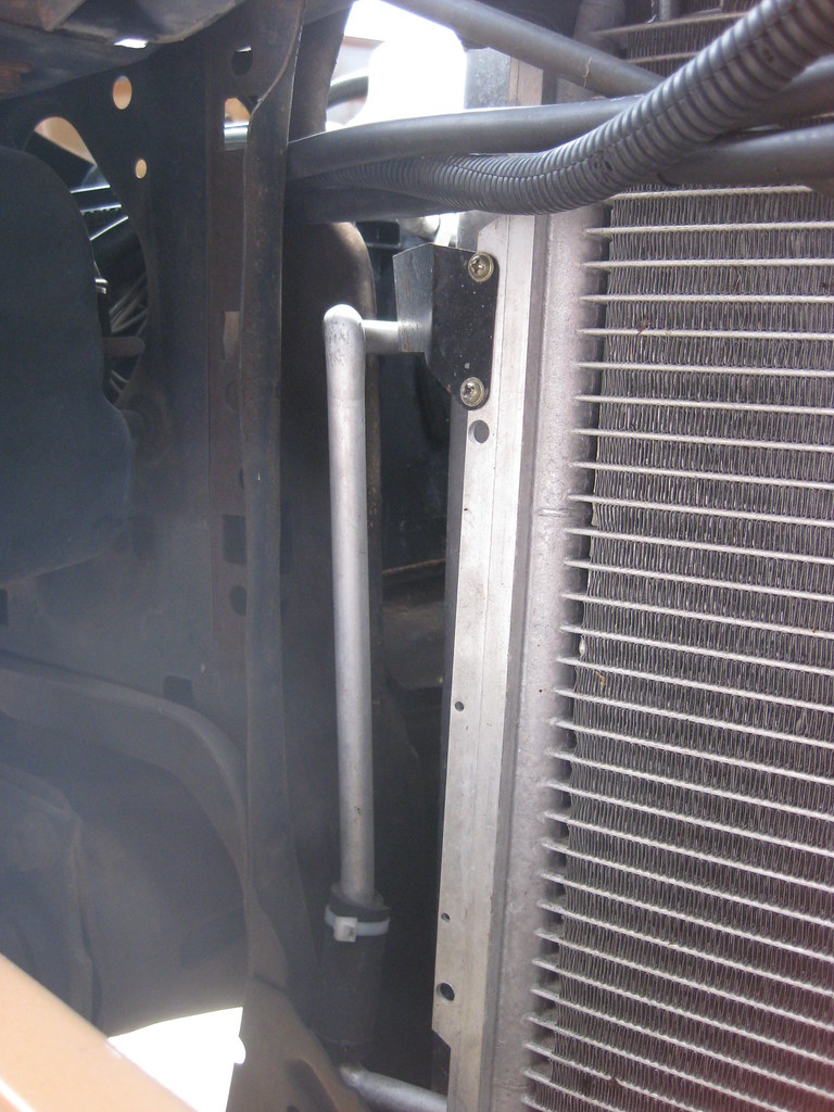
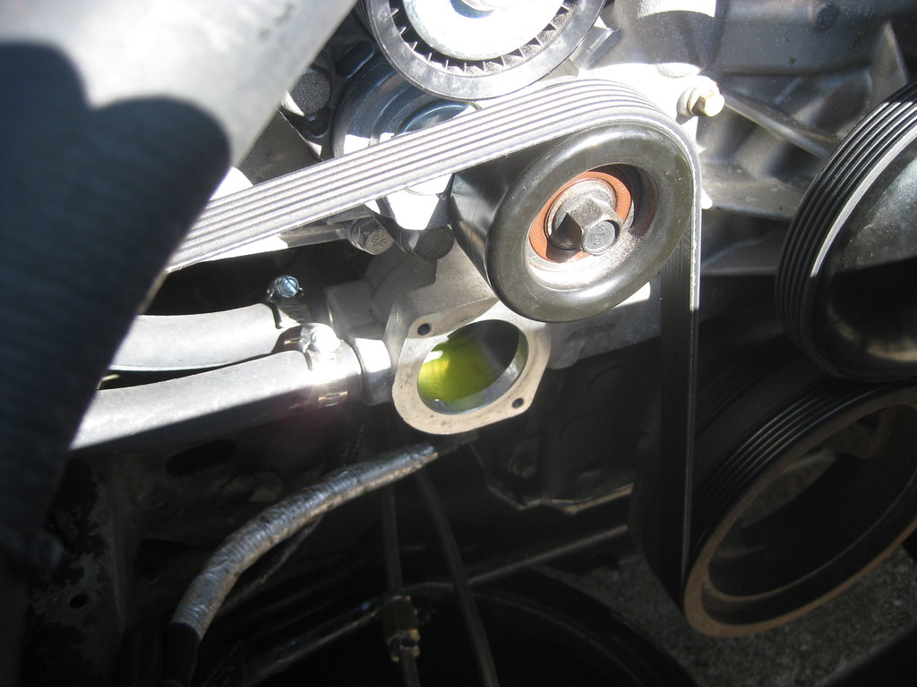
As I began to drive the car to work I noticed that the high speed fans were coming on even though the highest outside temperatures that week were in the 20s.  I was at first concerned that the car was overheating.  After looking into the issue I finally determined that the system was not setup correctly.  First, the parts house didn't have the correct thermostat back when I had bought a new one for the engine so I ended up with a 205 degree instead of the correct 187 degree thermostat.  Second, LS style engines run hotter than older GM small block engines that I am used to, so I had the tuner set the low speed fan to come on at 197 degrees and the high speed fan to come on at 207 degrees.  This meant that the thermostat was keeping the engine from cooling below 205 degrees and the fans were trying to keep it below 207 degrees, so they were fighting each other.  Once the high speed fans came on, they never shut off until you cut the car off.  It is normal operating temperatures for these engines to run between 200 and 220 degrees.  I purchased the correct 187 degree thermostat and plan to meet the tuner to have him reset the cooling fan settings to a more appropriate setting.  Hopefully this is all that will be needed to resolve this issue.

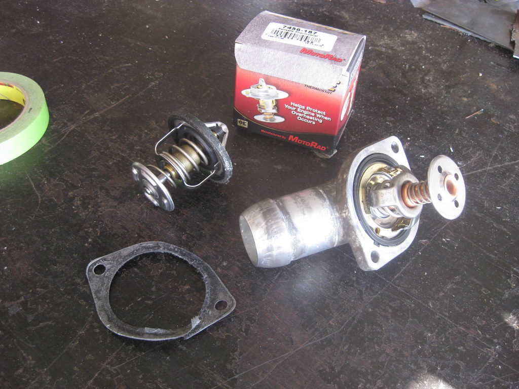
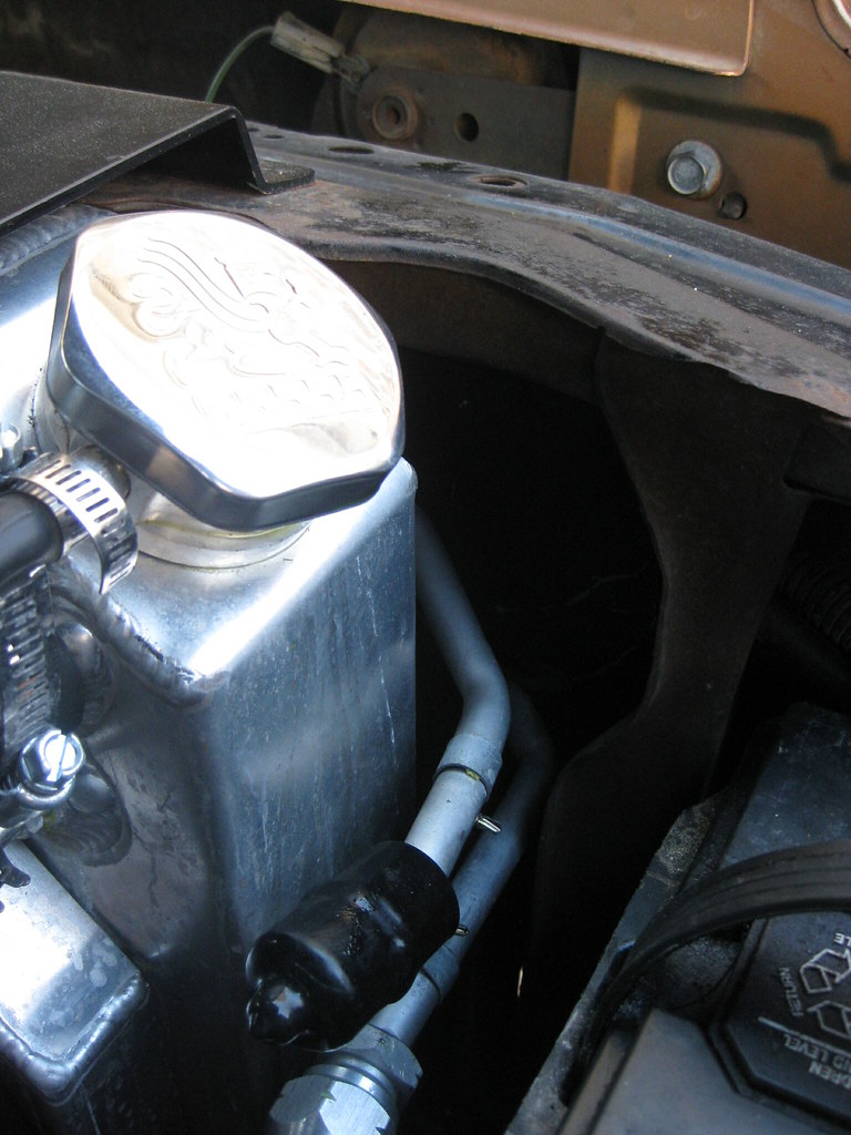
I found out that my setup had an extra gasket.  The thermostat had the gasket around it and the housing also had a gasket on it.  I think what happened is when I ordered the thermostat the first time they gave me the wrong year.  Earlier models used a thermostat housing gasket and later models used a thermostat gasket.  I ended up installing both because of the mismatched pairing.  To replace the thermostat I bought a new catch can and reused all of the lost coolant because anti-freeze is very expensive these days.

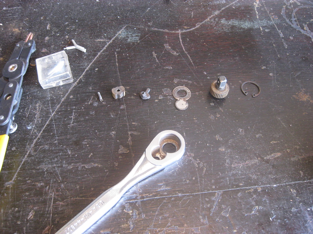
My wrench finally decided to quit working.  Fortunately a video on the internet showed me how to repair it.

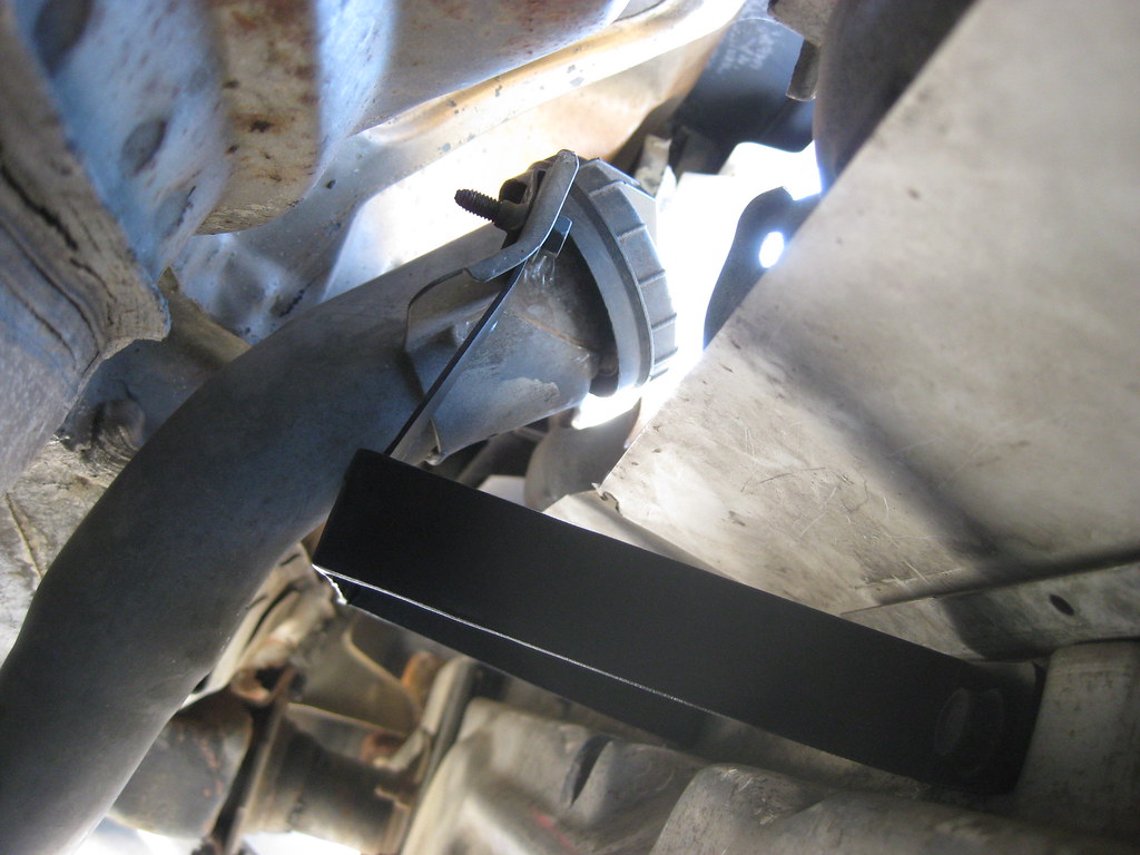
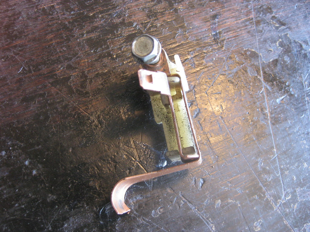
Another problem that arose was the brake warning light began to come on.  The proportioning valve and parking brake wires are spliced together and go into the warning light on the dash, so I had to check both systems.  While I had it apart, I found out how the parking light system works on older GM cars, which is backwards to what I had presumed.  When the light is grounded it comes on.  When the ground is broken, it goes off.  The tang near the top is where the wire from the dash light connects.  It is insulated and held in place with plastic.  Notice this piece comes straight down and turns right in an L shape, where it makes contact against the bottom piece of copper, which is in a backwards-L shape.  When the parking brake is released the arm comes up and pushes on the bottom, turned-down piece, which pushes it back and breaks contact between the two pieces of copper, causing the light to go out.  When you push the parking break down the arm is pulled away from the bottom, turned-down piece and contact is made between the two pieces of copper, causing a connected circuit to the dash light, which of course causes it to glow.  After spending way too much time laying in the floorboard and under the car, I finally got the issue resolved.

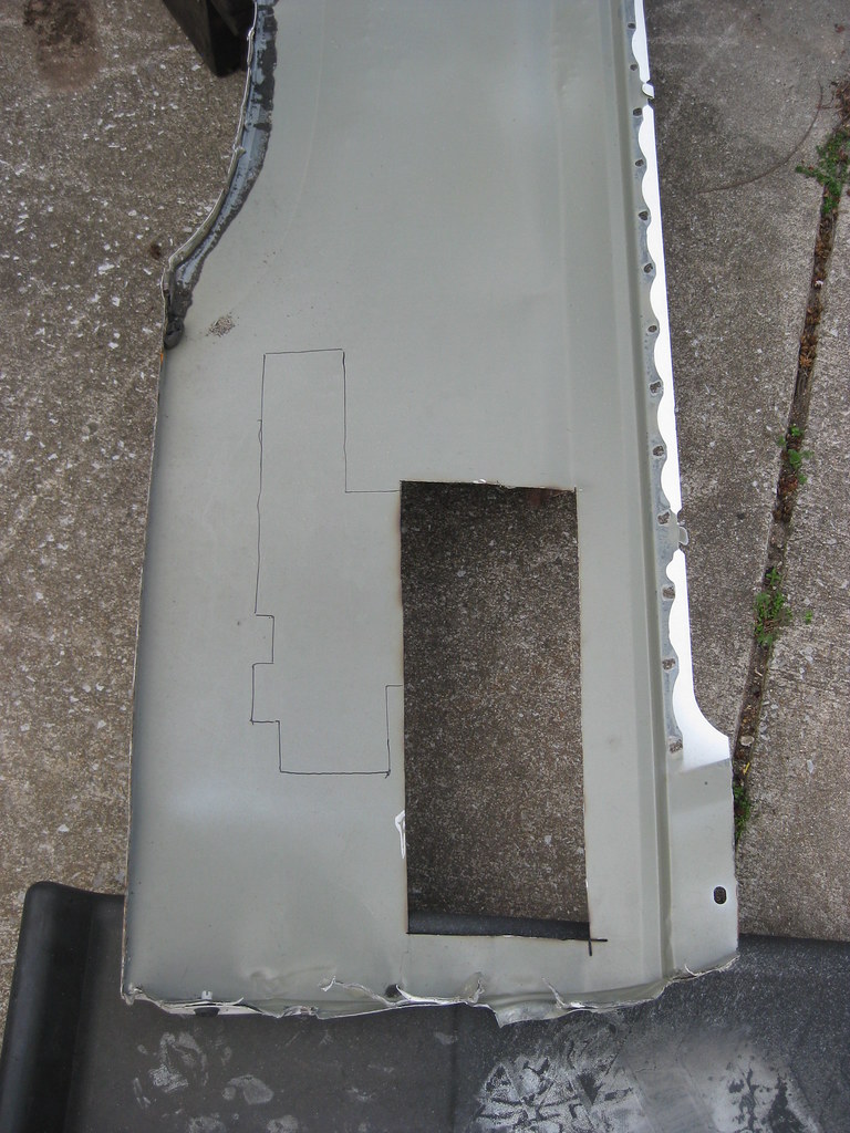
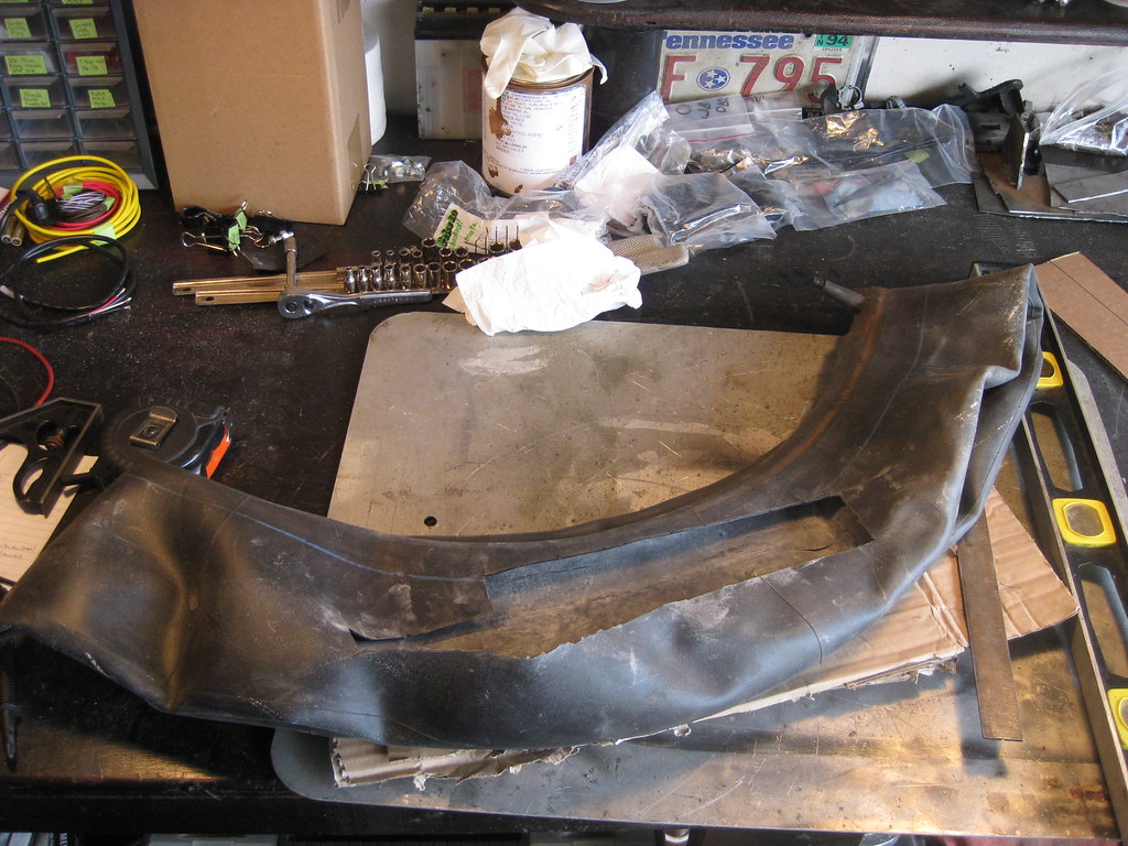
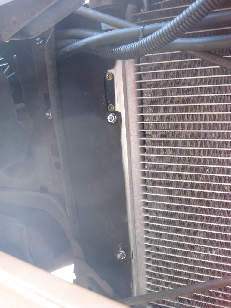
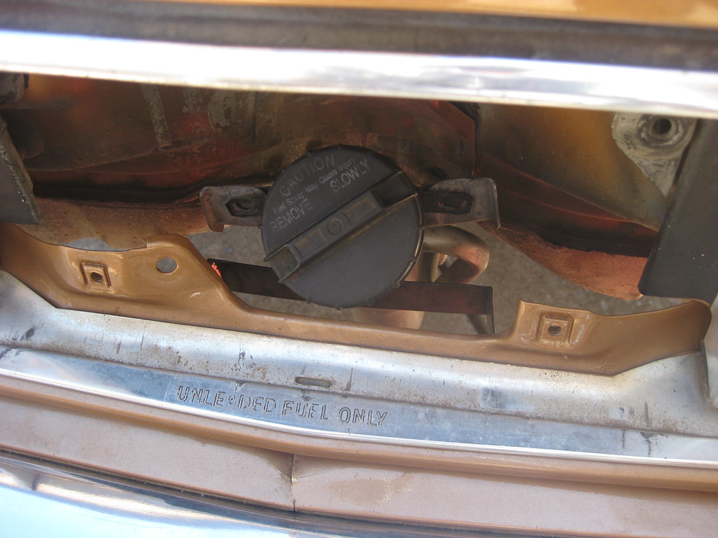
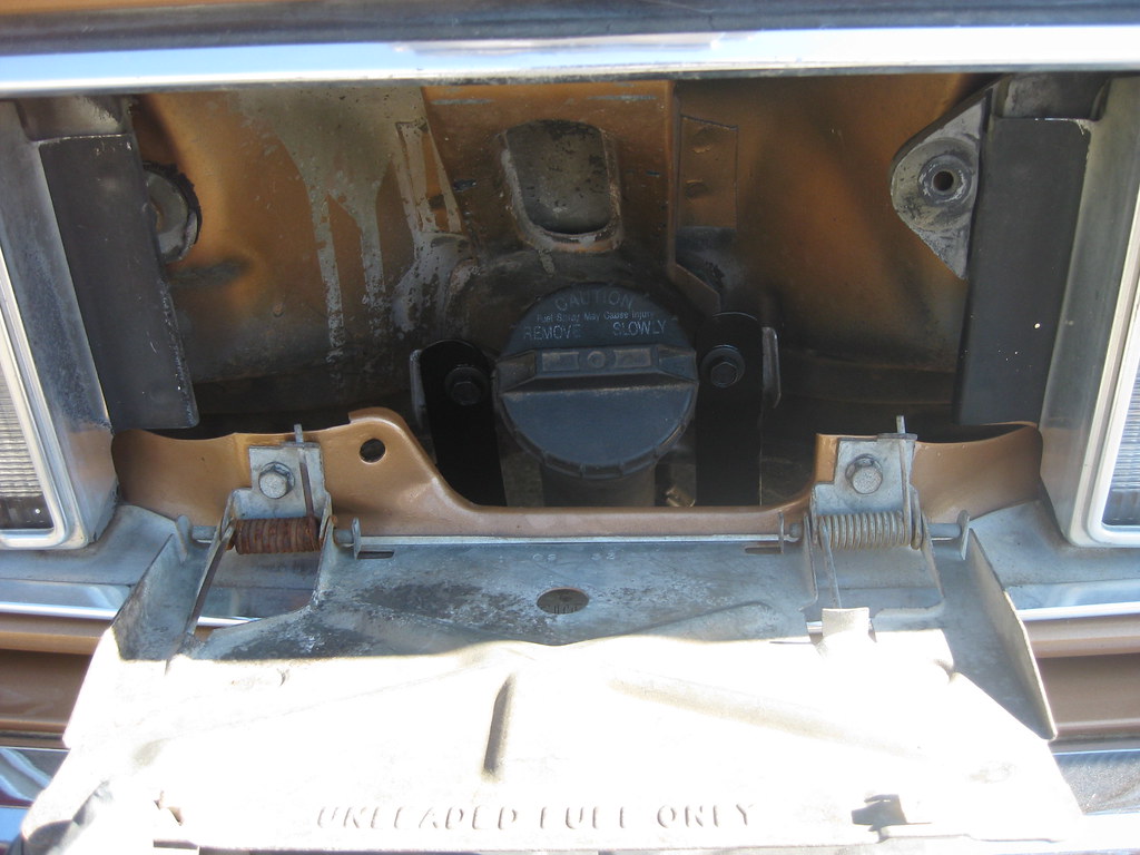
The following project, which shouldn't have been hard at all, turned into a huge problem.  What should have been the simple removal of two bolts turned into completely removing the bumper, drilling out all the bolts, going to every parts house in town and some outside of town and finally having to order hardware from an online company because no one in town seems to know what a "body bolt" is.  The local hardware store didn't have the sizes I needed.  At long last, I had all the hardware I needed, the bumper but back together with all new, non-broken clips and time to get back to work on it.  The filler neck was sitting loose behind the license plate.

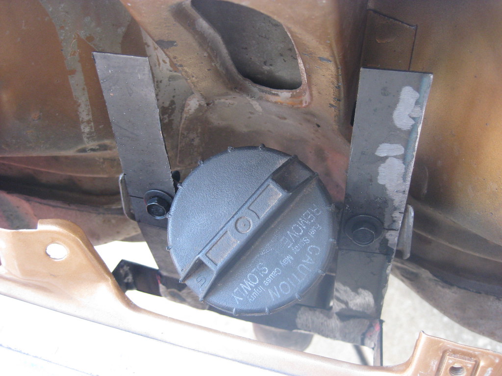
I bolted the first piece in place and thankfully the new bolts were long enough to accommodate the extra thickness of the new mount.

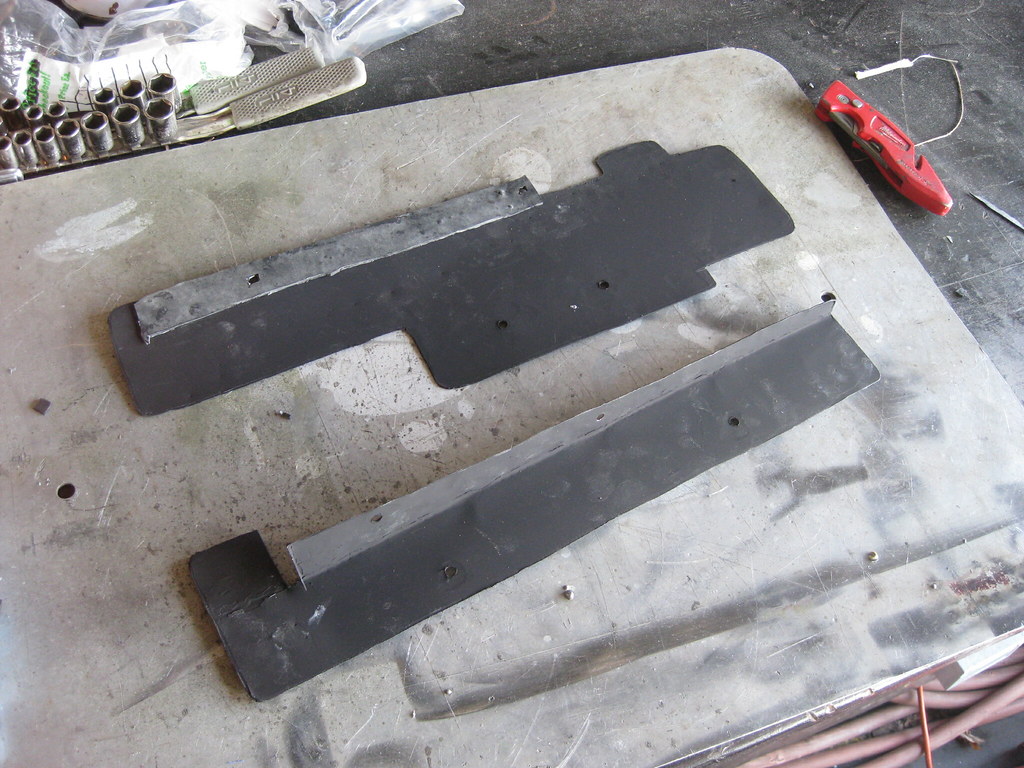
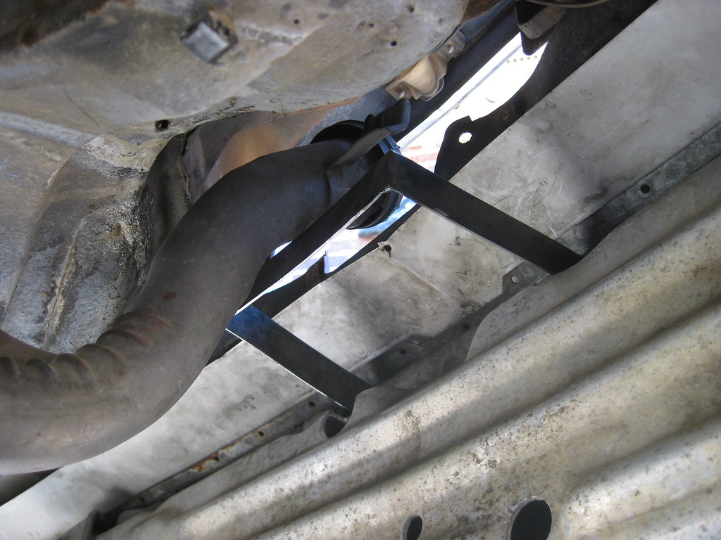
After a lot of on again, off again, measuring and drilling and welding I had both arms mounted.

At first I had planned to make extra supports for the brace but I found it was plenty sturdy to hold everything in place securely.

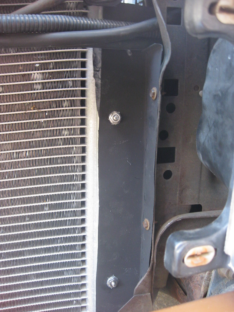
In the end my goal of using existing bolt holes worked out.  If I ever change the bumper all I'll have to do is unbolt this mount and attach it to the new bumper (unless the clips are all broken on the new bumper, too, which is likely).

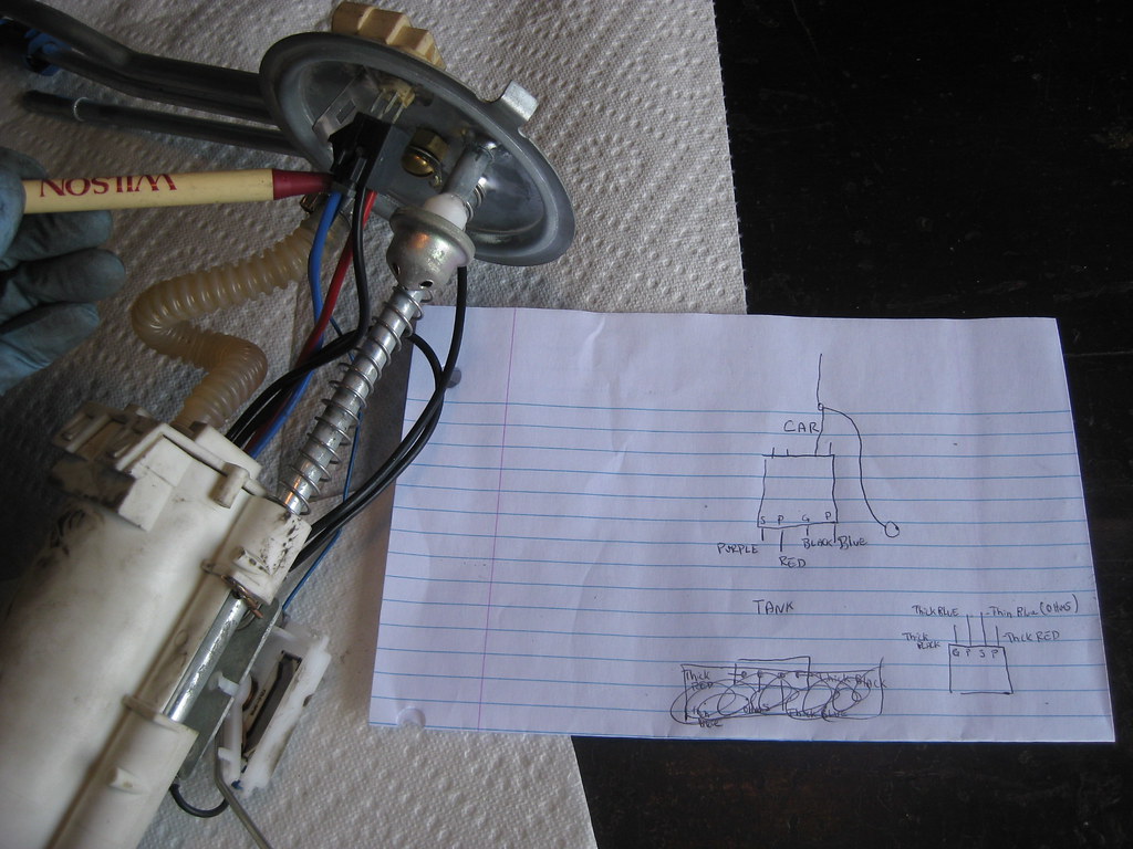
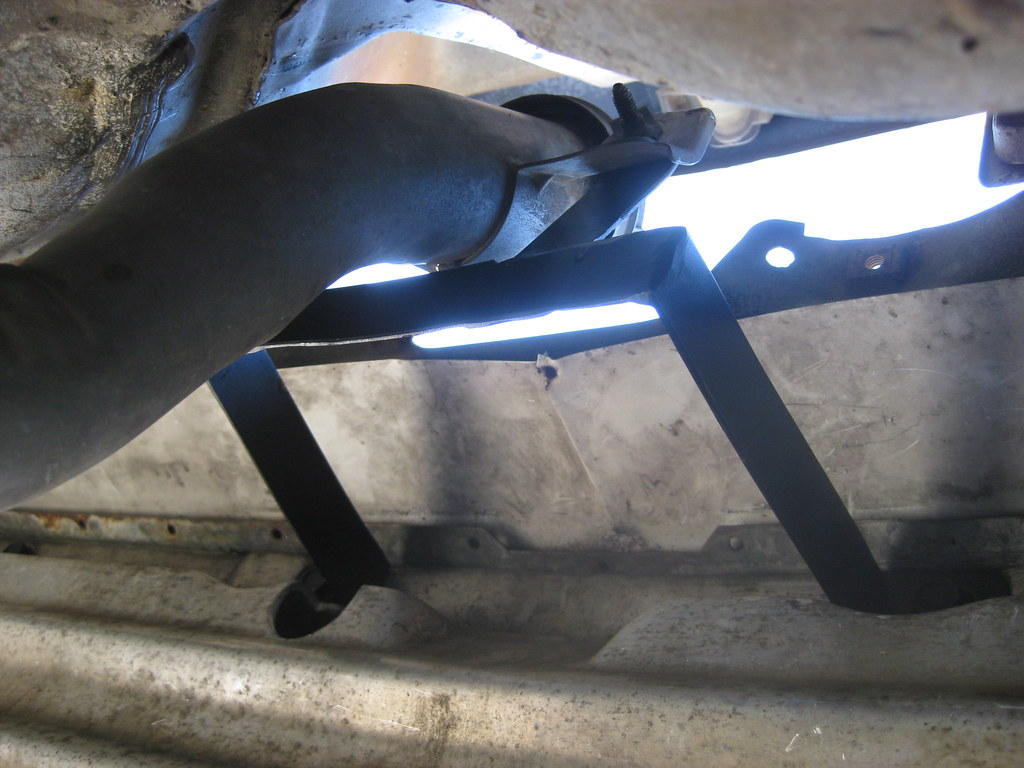
Here's what it ended up looking like from the outside.  Next on the list is diagnosing why the fuel gauge doesn't work.