Thursday, September 20, 2012

This Car Is Cooler Than I Thought

Today I finished up the rear bracket on the transmission cooler.  The front mount I made is mounted on the transmission crossmember, which sits higher than this supporting member.  That meant the front mount was higher than the rear mount, which meant that I would have to build legs for the rear mount to stand on.

I had to get a little creative with the clamps and vise-grips, but I eventually got it held in place to weld.  I've been having trouble the last two days getting the welder set correctly.  My welds have not been as good as I would like them to be and I can't figure out why just yet.


I had to cut a half circle out of each leg so it could sit on top of the round support arm.  Grinding the primer off of the the support arm under the car was probably the hardest part.

I only tack welded the rear mount in place, and I was only barely able to do that.  It looks like there is a lot of room to get under the car and weld it but in reality it's almost impossible to do anything but lay flat and look around.  I'll finish these up when I take the car back apart.

 Here's the finished, for now, product from the front.  The fittings for the cooler weren't right so I'll have to wait until I get the right fittings to cut the line and plumb it.

I then moved on to the radiator cooling fan.  The big question was would it fit between the pulley and the radiator without rubbing or hitting anything.

There were no installation instructions with the unit because each install is always custom.  I talked to the man from the cooling fan company in person at the Street Rod Nationals in Louisville Kentucky just a month or so ago, but I still called the company to make sure I was on the right track.  There is a metal tab that is bent around the rear of the radiator just to the right of where the head of the screwdriver is in the picture below.  According to the company, it's OK to drill into the radiator at this point because these rows of fins are supposed to be soldered and capped off.  Besides the fact that this is terrifying on such an expensive, brand new radiator, if I'm going to drill into a radiator I was going to have to hear the go ahead straight from the company that made the radiator, Walker.  I called them and they said to go ahead.  Reluctantly, and still somewhat in disbelief, I went ahead.

First, for better cooling, they said to trim the top and bottom edges of the plastic fan shroud.  I used a the grinding wheel to get the straightest cut I could.  Unfortunately, this of course melted the plastic rather than giving it a perfectly crisp cut.

This was a job for the magical silver sharpee, so I used it to make a straight line to cut by.

I did this to the top and bottom

Then after trimming the top and bottom I measured and drilled two oversized holes for the four provided sheet metal screws

After that, I drilled the top two holes, one at a time.  I first held the fan up, marked the first hole, drilled it, and then mounted the fan to mark the second hole.  I marked and drilled the bottom two holes at the same time.  This was my first, very reluctant hole.

I used a punch to try to minimize the drill bit from walking around.  This was the one hole that scared me the worst.  When the drill finally went through the metal it punched deeper than I wanted into the fins.  If it leaks I'll be going back to the company with it.

I had been really dreading doing this installation but the actual mounting process was one of the easiest jobs I've done yet.  When I called Walker they told me to mount the fan as high as possible.

Here it is installed.  It fits, but there is definitely not much room to play with.

Wednesday, September 19, 2012

Parking Brake Conundrum

I thought I would breeze through hooking up the parking brake and getting the trans cooler installed today.  I suppose that's what I get for thinking.  Though I knew the parking brake setup was kind of strange when I'd looked at it earlier in the build I found out today that it's not as straight forward as I had hoped it would be.  The Ford parking brake system used on several of its models, including the Ford Explorer, from which I'm using the rear end and parking brake assembly, is not a standard two cable system.  Instead it uses some sort of strange varying-degree of force system.  I'm not sure I can fully explain it and having not been able to see one actually used, I'm not 100% sure I completely, as of yet, understand it.  I searched for most of the morning trying to find information about this setup and after not finding any answers went to the Ford dealership here in town.  The brake guy there was very helpful but we both couldn't fully understand the situation until we looked under a newer model which has a similar setup.  I then found the same model Ford Explorer on a used car lot and sat under it for a good 10 minutes trying to determine exactly how it works, but without having someone engage the parking brake while being under the vehicle to watch it in action it's difficult to envision.

Here's a picture I took of the first unit I have that came with my rear end.  I had initially cut this one too short so I had to go back and get a second one, but this will work for my purpose here.

On the Explorer, the parking brake handle under the dash is connected to the cable (A).  The cable moves inside of the rubber casing (D), but the rubber casing (D) does not move and is stationary.  The cables (A) and (C) each run to their own respective side of the car for the two rear parking brakes, driver and passenger side.  The cable (C) is attached to the back of the bracket (B) which is in turn attached to the front of the rubber casing (D).  The problem is that the rubber casing (D) doesn't move, and since (B) and (C) are attached to it and the only way they can function is if they are pulled, there's no way for them to work.  The cable (A) slides independently, inside the casing (D).  After talking to various people and looking under an actual Ford Explorer, the only thing I can determine is that cable (A) and its casing (D) must have an exact amount of slack after the point which it contacts bracket (B) which will allow (D) to enter the bracket (B) at an angle, and bracket (B) must be pulled tight against cable (A), giving cable (C) tautness against where it is mounted by clips in the big black bracket shown.  If this is true, when cable (A) is pulled it would then pull upon bracket (B) which would cause cable (C) to pull tight, but that is only given that once the slack is taken up in (D), it will allow both cables to pull at the same tension.  Even though cable (A) is the same cable that runs through the casing (D), because it is mounted in bracket (B), this allows (A) to be held tight forward of bracket (B) but have slack after bracket (B).  The only reason I can think of for this being the way it is is that if one brake froze it would still allow the other brake to partially engage, and that's only maybe, if my thinking is correct.  I'm still not sure if the forces acting on each cable would be equal or if one engages before the other in a progressive style.

The problem I have is that I have already mounted the large black mount to the frame and there is no slack in my casing (D).  There is slack is cable (C) and casing (D) is taught.  This is backward to what I believe it should be.  Moving the large black mount back would correct the problem, however the fuel lines have been run above the large black mount so it cannot be moved back to test this theory.

I have decided to wait until the body is back off so that I can better access this problem.  My solution will end up being something like this:  I am going to remove the bracket on the left in the picture below, that my finger is on. and replace it with a factory cable connection, like what is pictured on the cable to the right below the black casing, near where the black O-ring is visible.  I will then cut the line on the right so that it matches the length of the newly extended cable on the left.  The cable from the front will go back and mount in the center of a plate and each cable from the rear will extend through one side of the plate.  When the parking brake handle is pulled it will then pull equally on each cable.  This is how many emergency brake cables operate and is also how the expensive aftermarket cable made for this Ford 8.8 rear end is designed.  What I do not like about the aftermarket design is there are no casings for the lines to run through so you must design pulleys or have the cables run a straight shot to your rear wheels.  The casings on the factory setup allow me to run the cable far and out of the way and makes it much neater as well as frees up space that I'll be using for other things like a driveshaft, mufflers, exhaust, driveshaft safety ring and whatever else comes up between now and then. 

Here's a picture of how I connected the cable to the parking brake handle assembly.  When it's taken back apart I'll finish the welding, but for now it holds enough for me to figure how how I'll set it all up.

Monday, September 17, 2012

Parking Brake Mount: Finished

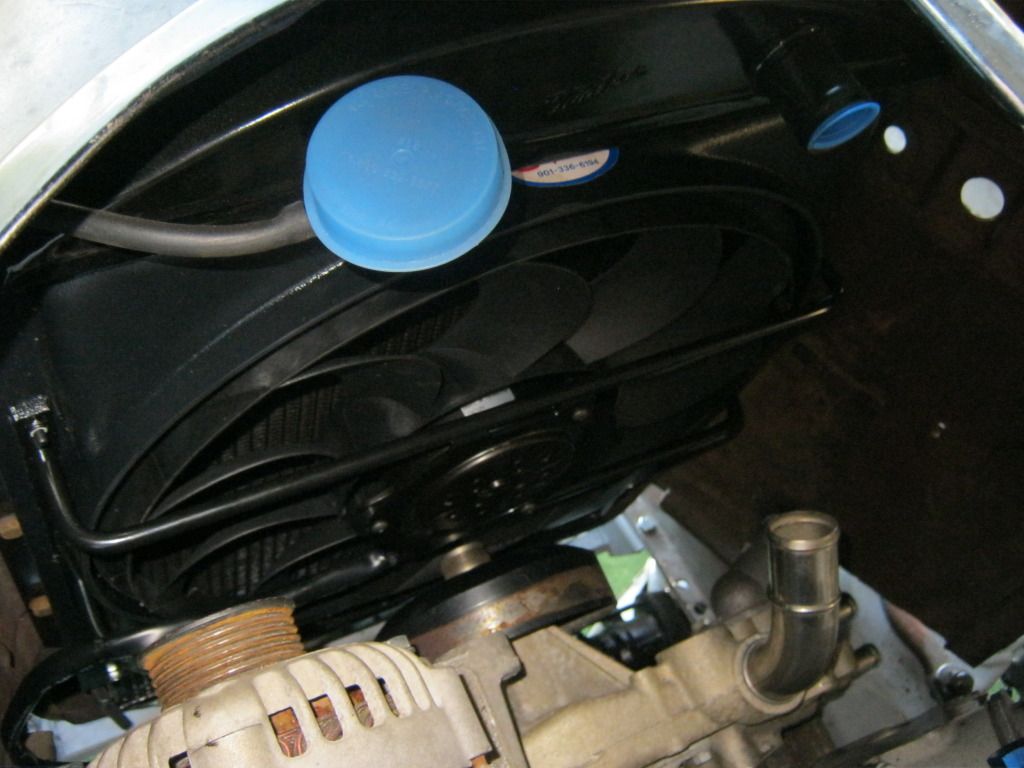
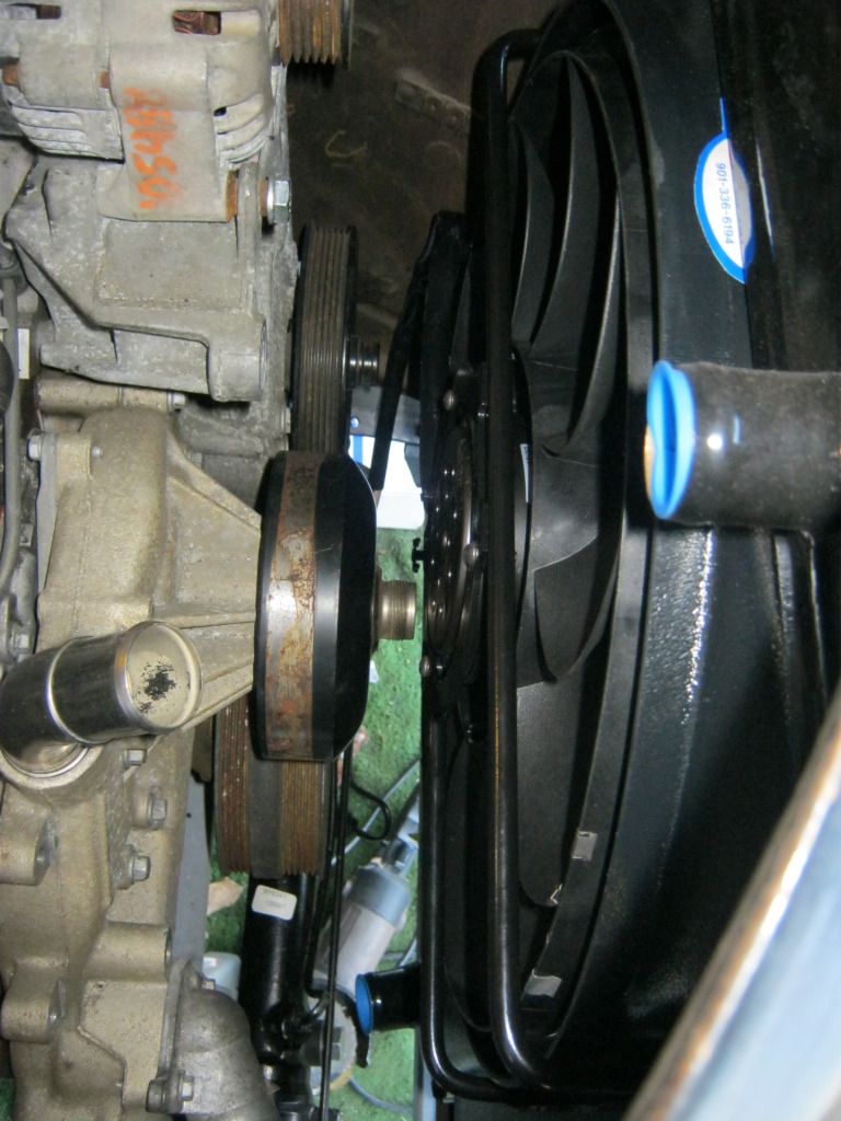
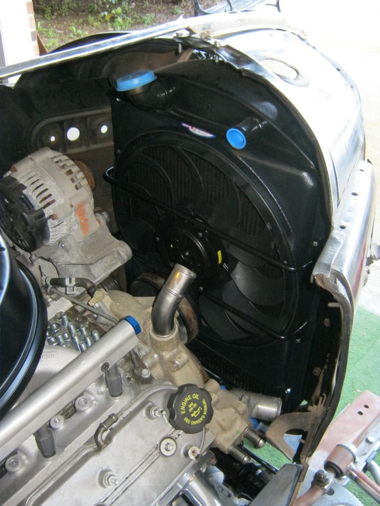
I continued working on the front accessory drive mounts and compressor brackets for a while.  Nothing that would merit any pictures, just more trail and error with fitment and pulley placement.  I finally got all the measurements and designs worked out for now.  The only real way to know is to see if the engine will eventually throw the belt.  I took my plywood templates to the machine shop and they are going to draw them out on the computer and cut them out of steel.  That meant it was time to move onto the rest of the long list of things to get done.

Before I moved on to more work with the '37 I had to get my '31 out of the barn.  A person in town hired me to drive in their daughter's wedding, which would be great except for the overheating problem I've been having due to the water pump.  I hope it's only a water pump issue.  At this point, it's showing signs it could possibly be a cracked head, but it definitely is not helped by the pump.  These old style pumps don't use bearings like newer pumps and instead use packing, a graphite type material that is squeezed around the pump shaft and sandwiched tight with a nut on the front of the pump.  Though I have rebuilt mine twice now, the kits available aren't always perfect and can allow air into the cooling system, which is the problem I'm having.  This causes the engine to blow coolant out of the overflow hose even when the car is not overheating, which quickly causes the car to overheat.  I have had plans to make a homemade recovery/overflow jug for the '31 for some time now and this seemed like the necessary time to get it done.  Unfortunately after I made it the car was spewing coolant so bad it became unnecessary because the jug wouldn't be enough to help at this point.  So I have it made and I'll eventually install it, but only after the new style pumps made with bearings are finished with their production and I can buy and install one on the old engine.

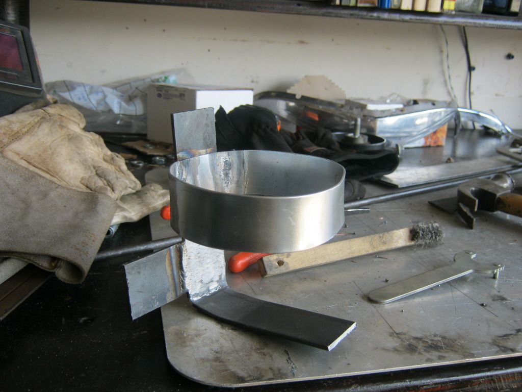
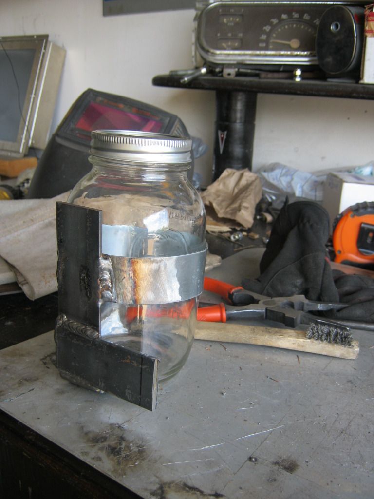
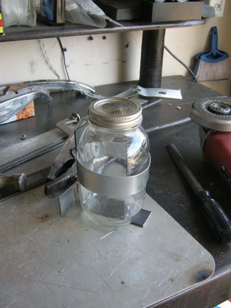
I decided to use an old mason jar as a recovery jug.  It seemed to look right at home with the '31.  I used some scrap steel I had left over and one extra gas tank strap to make the mason jar mount.


It wasn't easy getting the strap into the right shape and size to create a snug fit that would allow the glass to be steady and not break but at the same time allow it to slide out by simply pulling on it.  I will eventually add a thin rubber strip to the bottom plate for the jar to sit on.


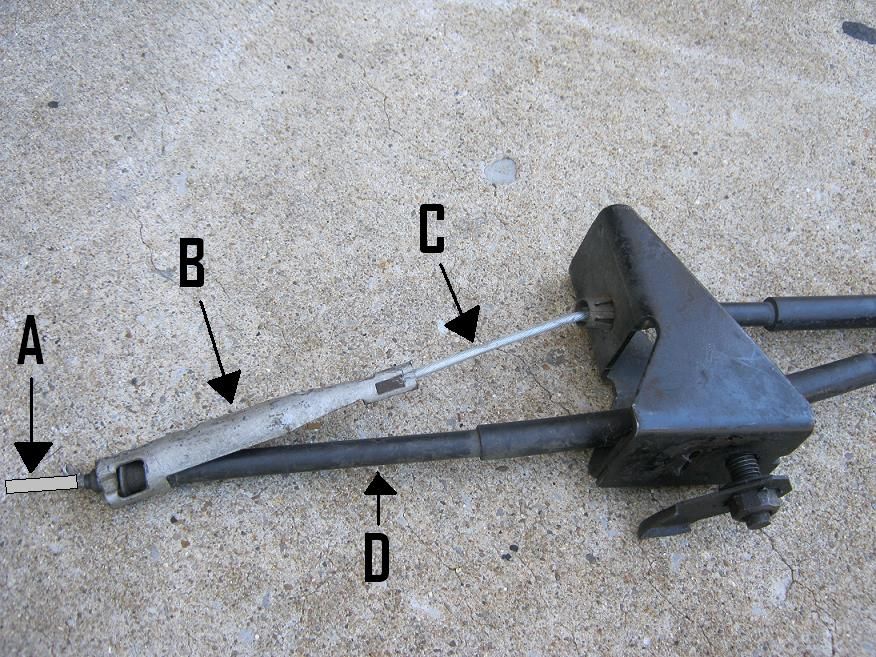
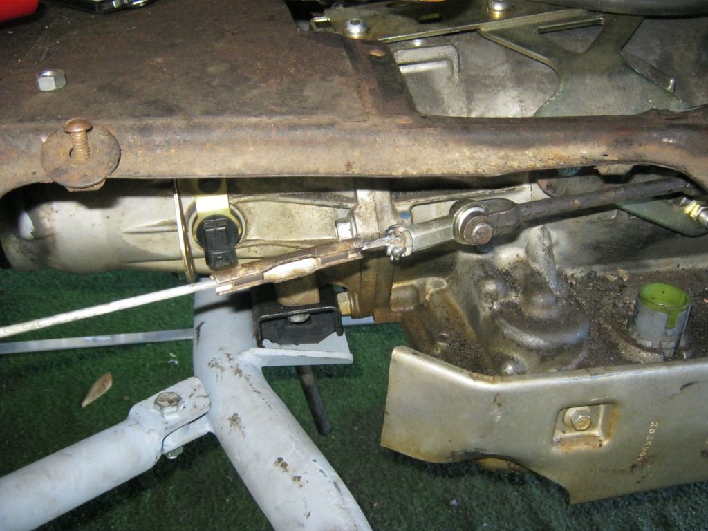
It was time to move on to the parking brake mount.  I had put this step off until after I had the air conditioner mounted under the dash so I would know where the right placement for the parking brake handle would be.  There were two holes on the side of the shifter mount.  These holes are actually there for a parking brake mount, however the mount that is offered is overly expensive and doesn't fit my application.  The holes, however, came in very handy for making my mount.


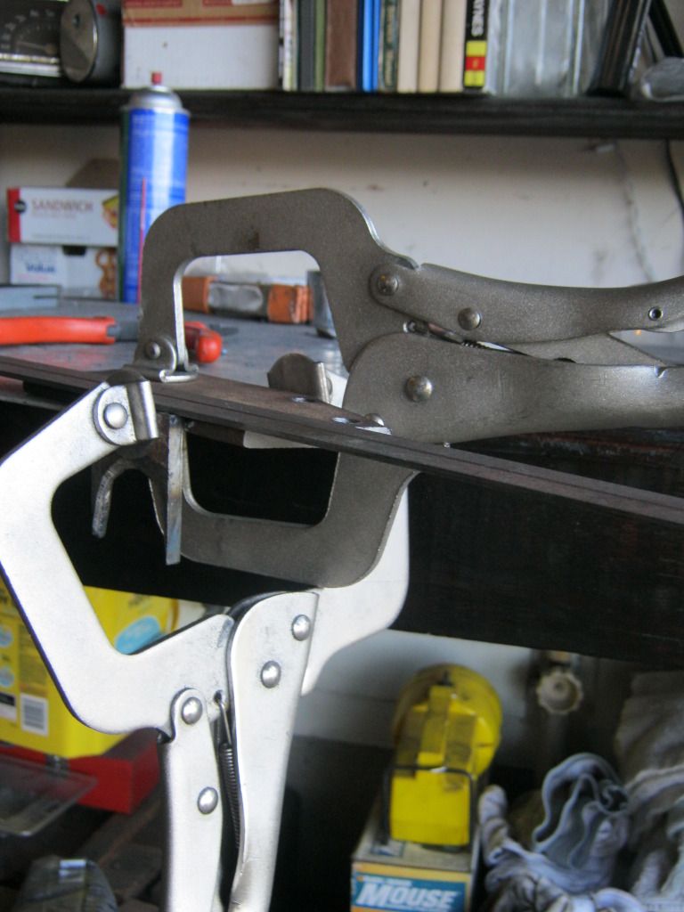
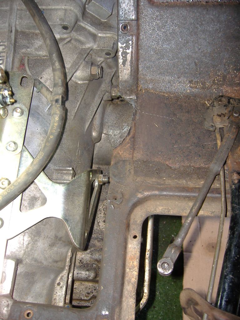
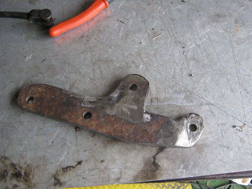
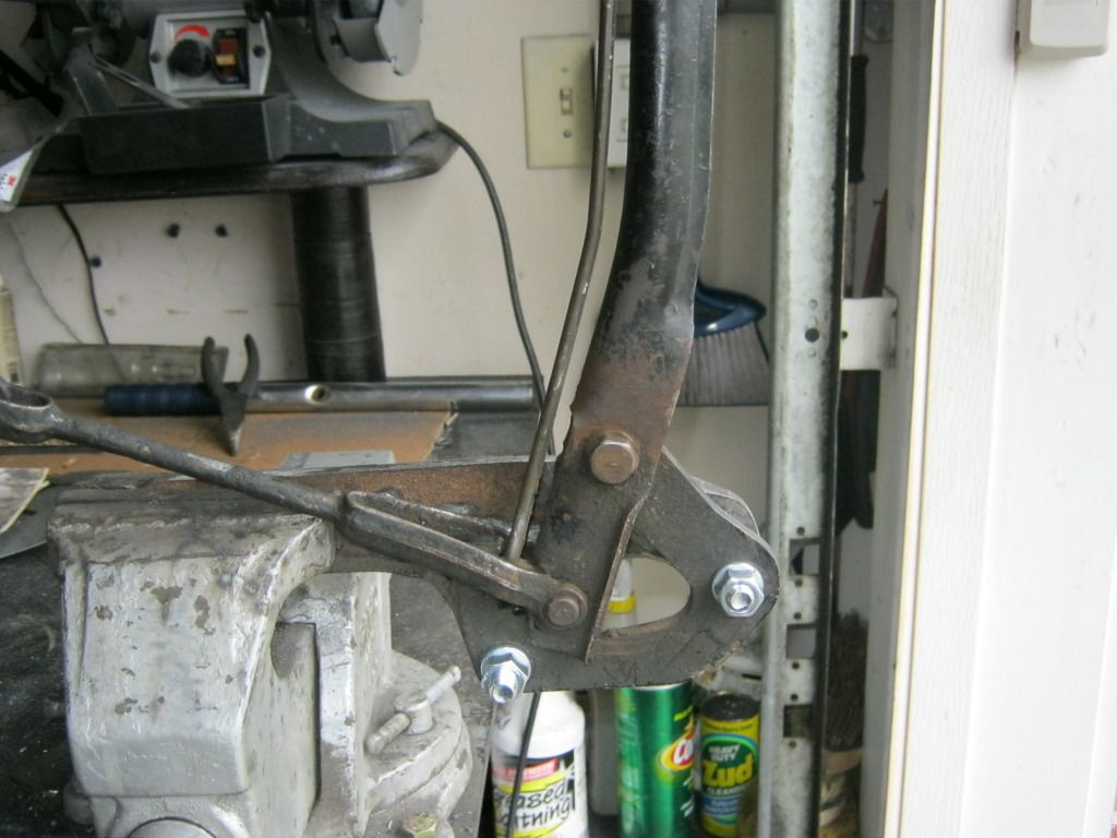
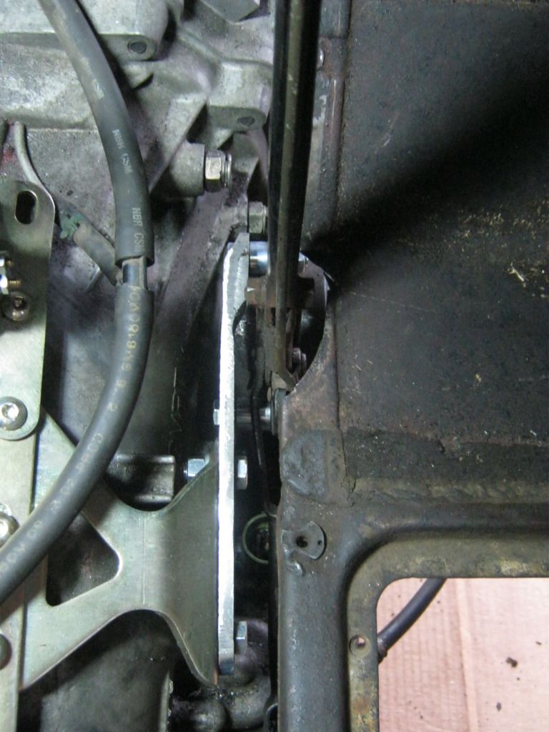
After making cardboard templates I used a large piece of steel I got from the scrapyard to cut out a length of metal for the mount.  After getting the holes drilled I was able to get the measurements of where to weld the tab for the rear mount of the bracket assembly.  Pictures can't describe how difficult it was to hold the entire assembly in place and try to mark measurements in the tight and cramped area I had to work with.  A 3rd arm would have really come in handy.  The gold bolt on the left is where the bracket must extend to.

I had to stop the bracket from going all the way to the front because the transmission bell housing flares out and prevented it from going all the way.  I also couldn't just bent the bracket to go flat up against the parking brake assembly because when the parking brake is pulled down the arm would interfere with that location.

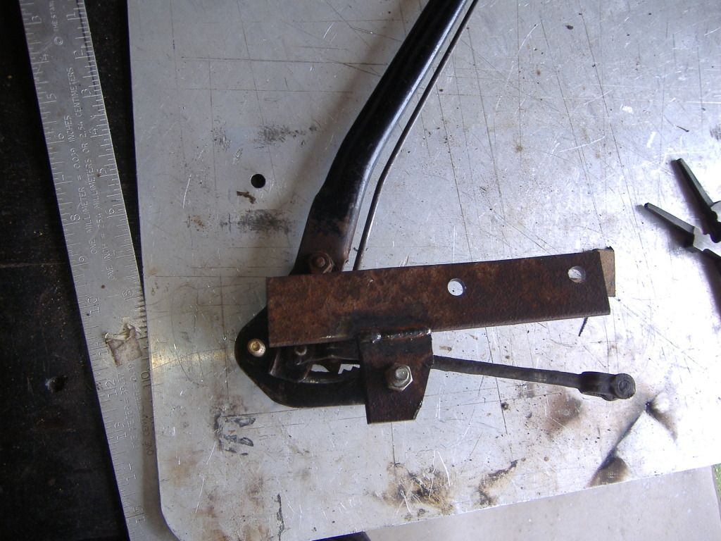
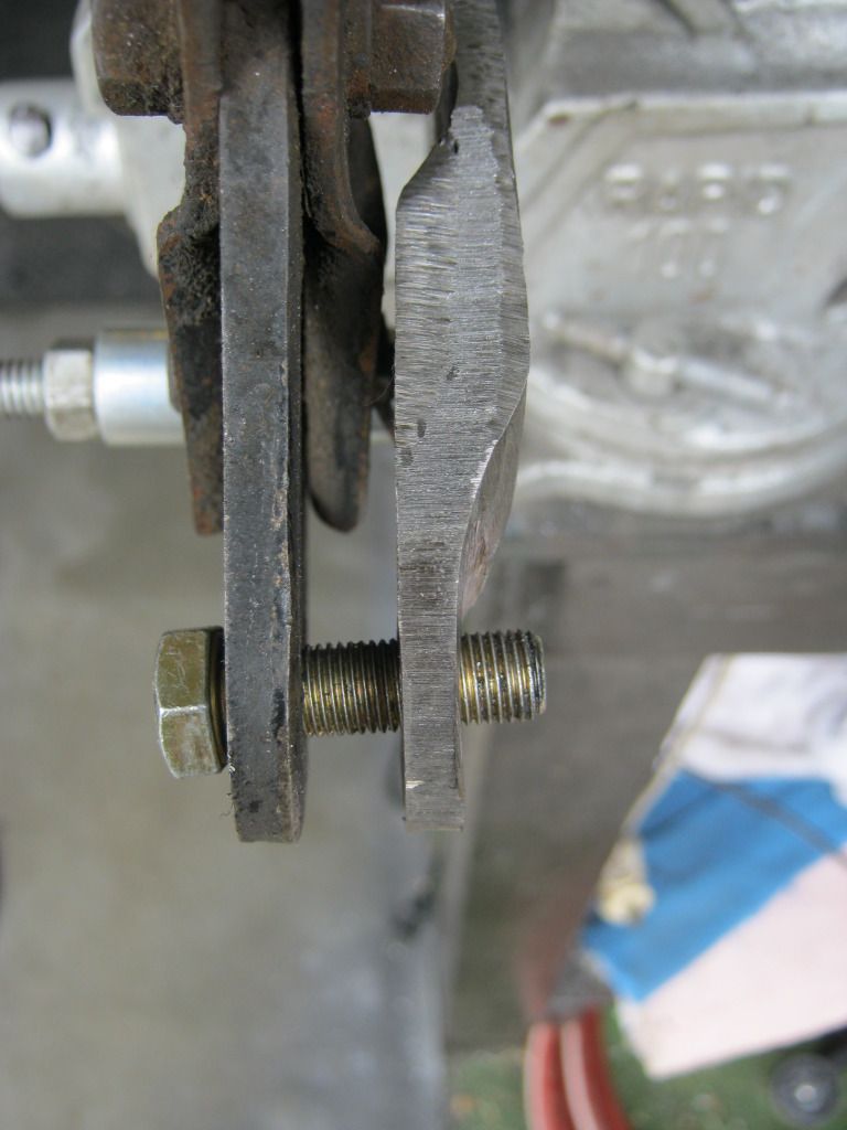
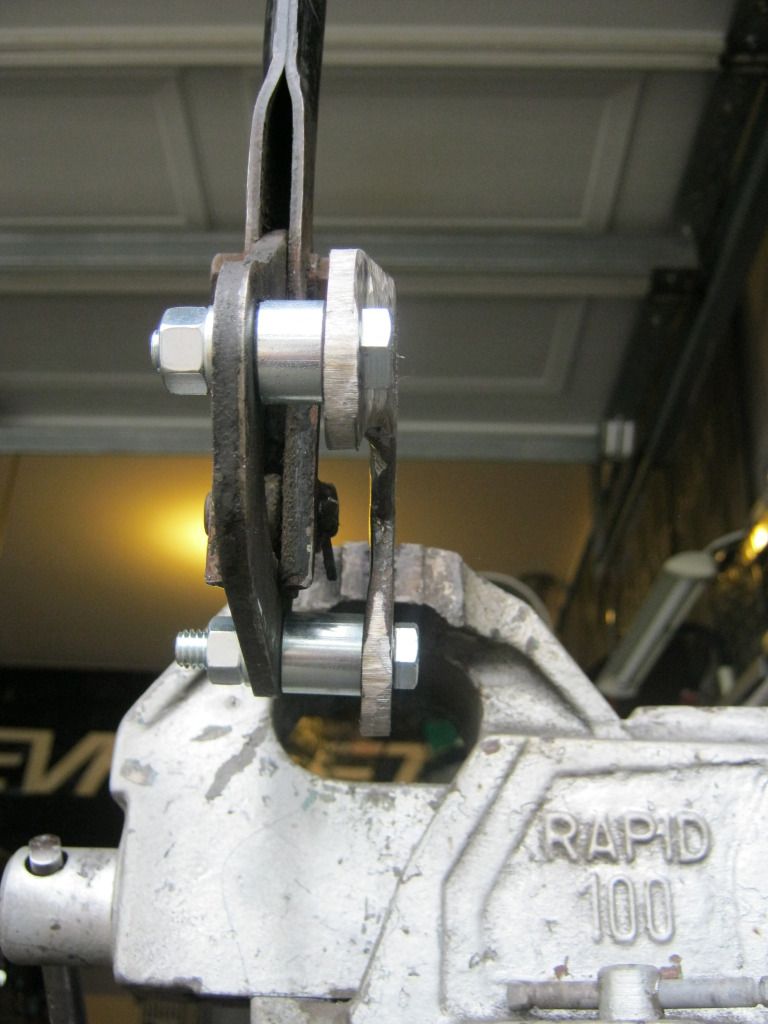
My solution was to weld another piece to the inside of the bracket and use a 1/2" spacer up front where a 3/4" spacer was used in the rear.  This cleared the transmission and did not hit the parking brake assembly when the lever was moved throughout its range of motion.  It was, however, very, very close.

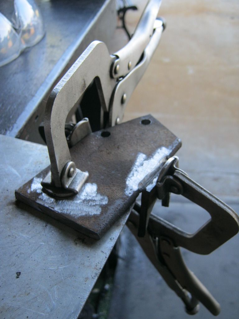
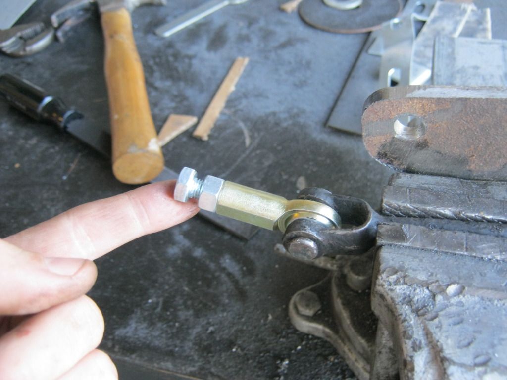
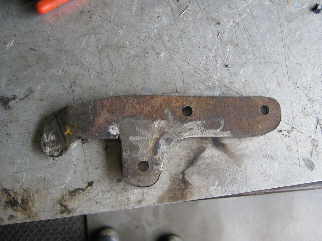
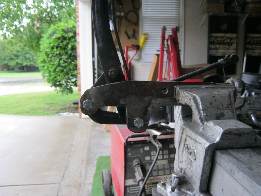
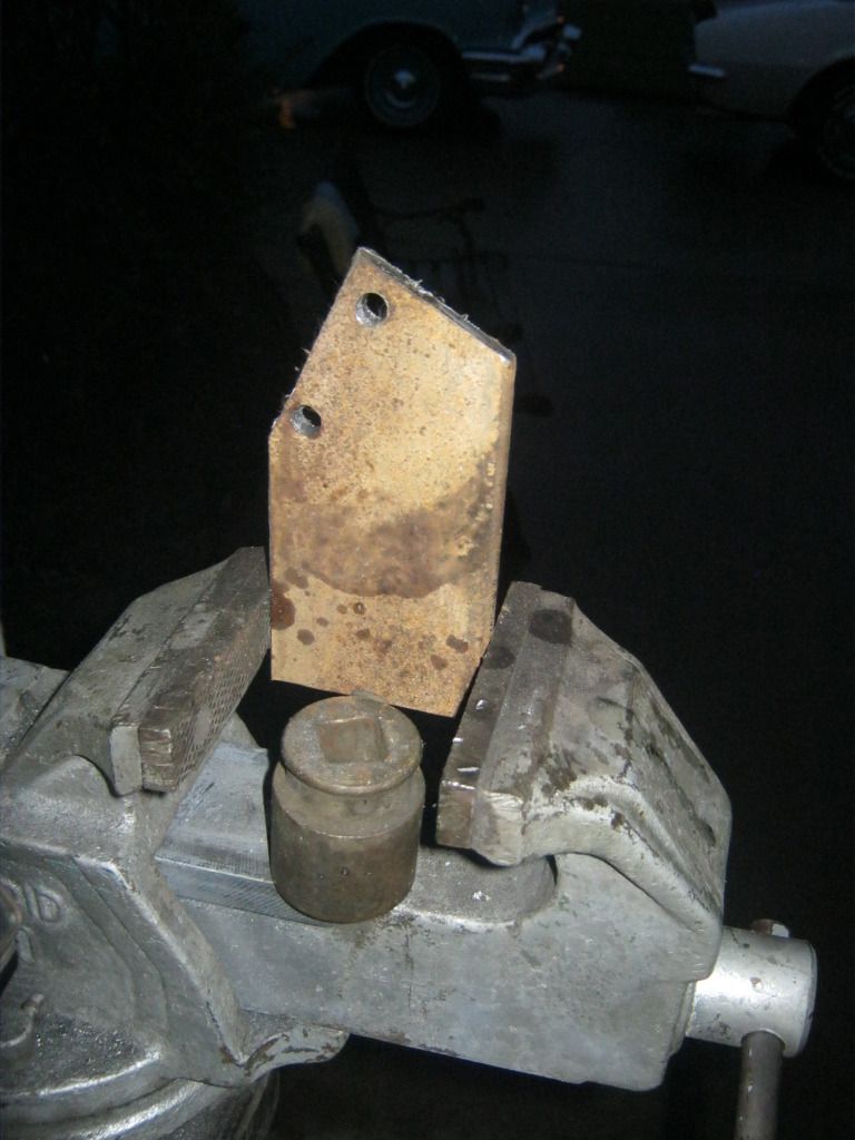
I had to grind a flat spot on the end for the bolt to mate up flush with the bracket.  After some shaping, welding and grinding it ended up something like this.

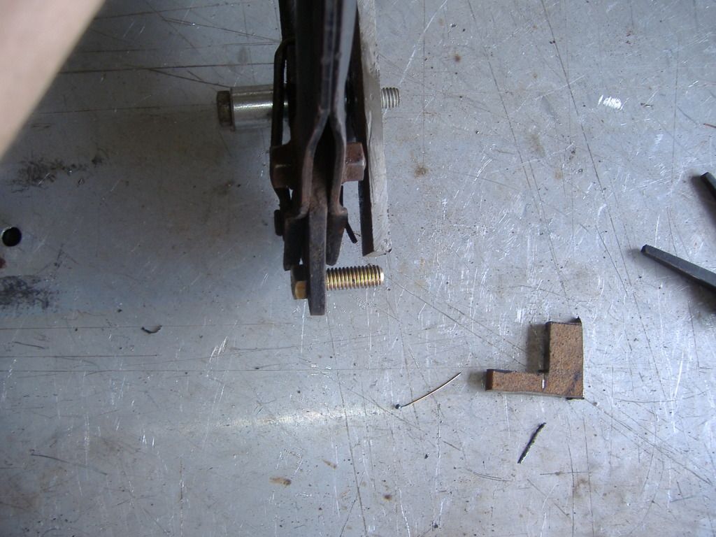
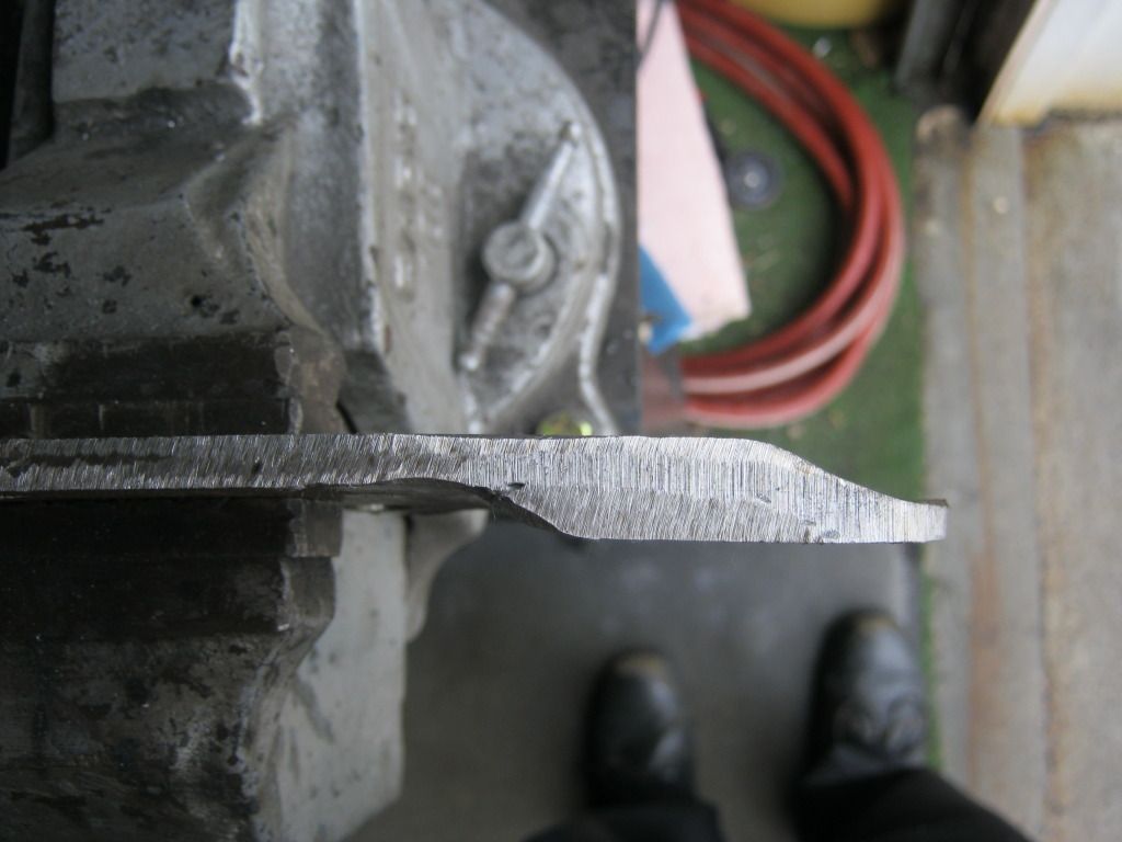
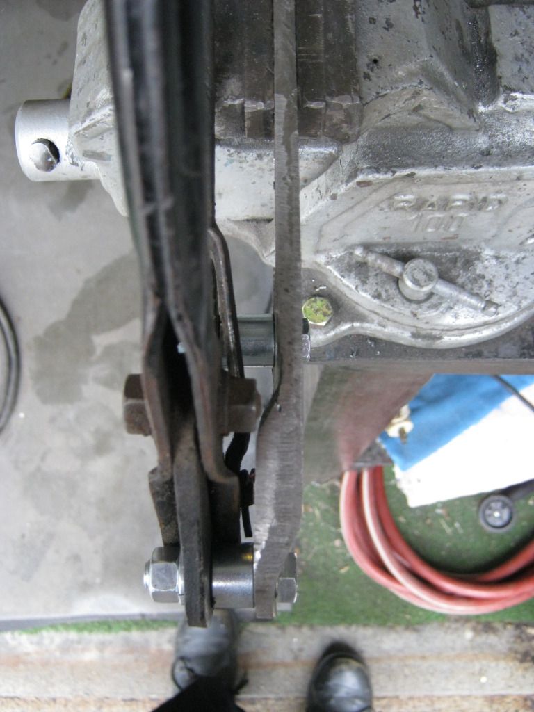
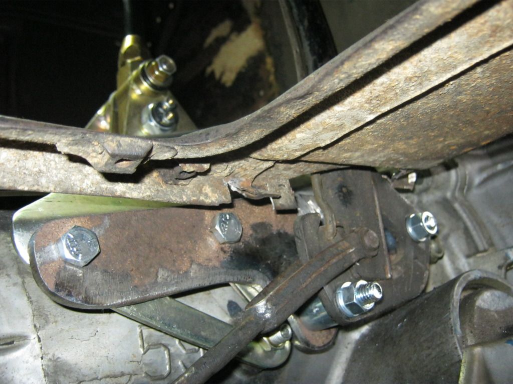
Here's a top view of the step-over that was necessary to miss all the objects in the way, like my shoes and that garden hose, hehe.

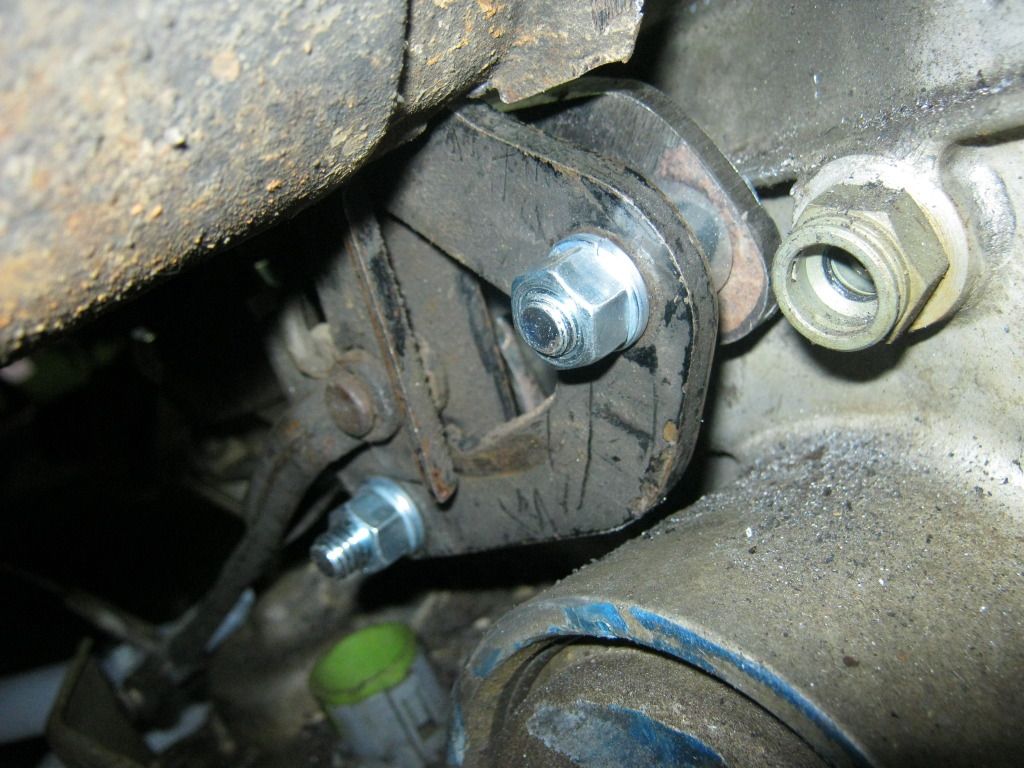
Here's the front mount before the spacer


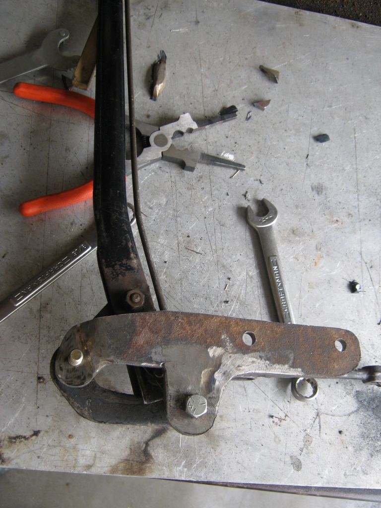
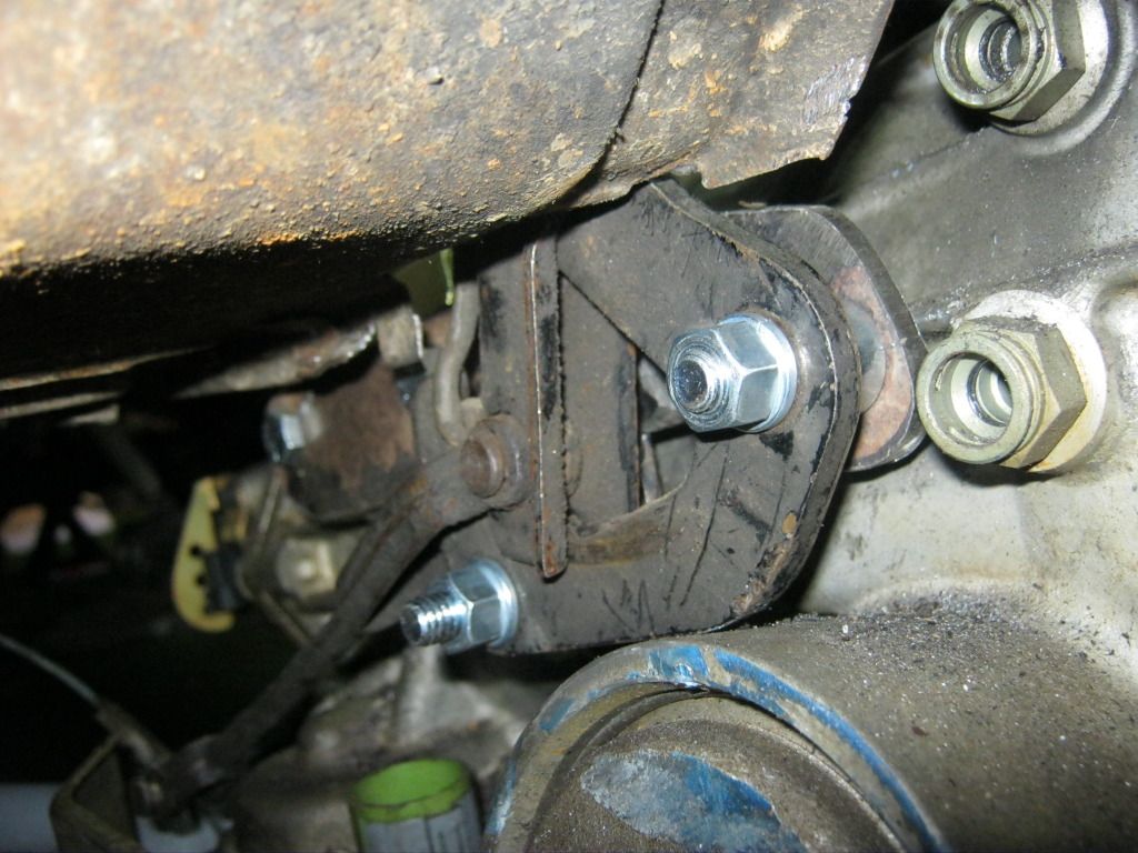
Here's how it ended up after all the spacers were bolted up.  The handle can now smoothly travel through its entire range of motion with no interference.


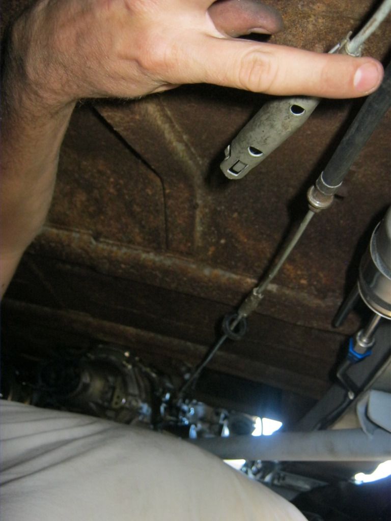
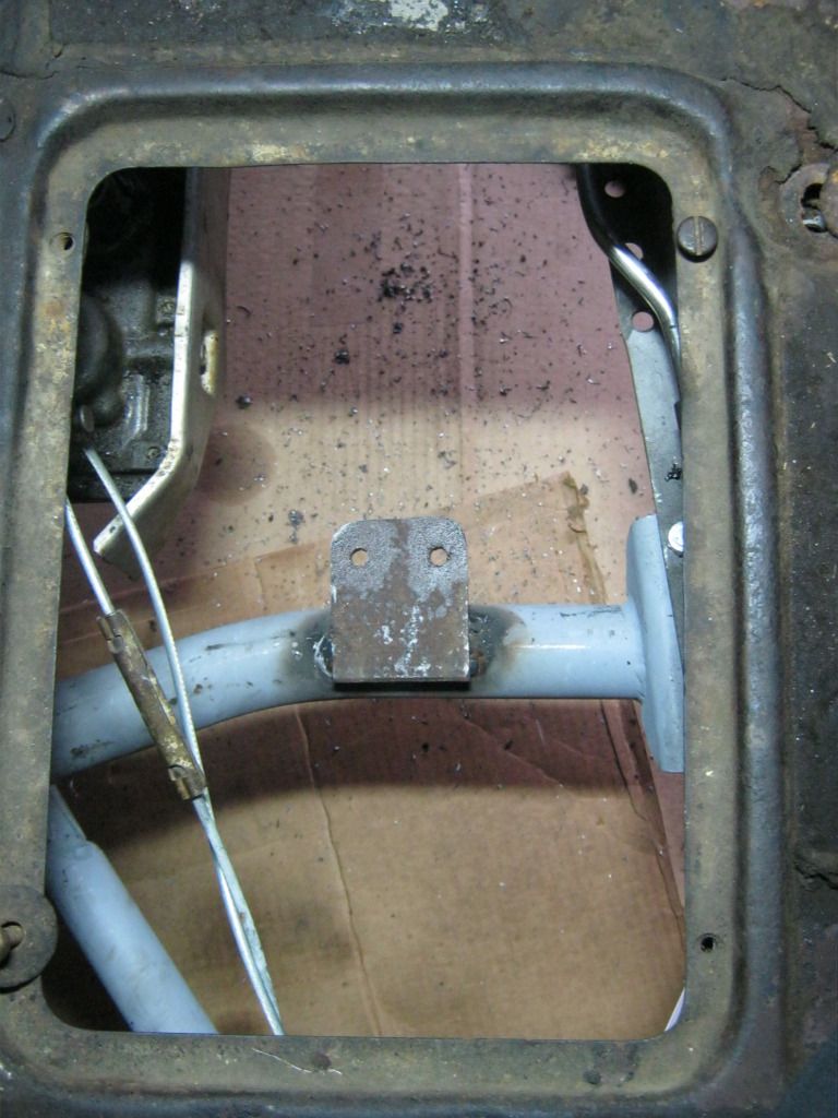
Here it is installed on the transmission.  I had to trim some of the floorboard away.  I'll clean this area up after I take the body back off and have better access to it.  I'm still contemplating how I want to mount the cable to the parking brake assembly.  There are many different ways to go about it.

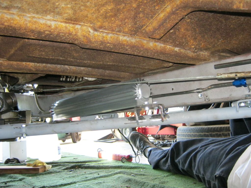
And here's a view from below deck

There was very little room to play to make sure everything would work as it was supposed to and that the handle was positioned how I wanted it.

Here's a good shot of the location of the transmission inlet and outlet that I'll be working with later on.  They are just to the right, top and bottom, of the parking brake assembly.


This whole process took about two days.  I had to finish this project so that I could find the alignment on the parking brake cable.  This would show me where I could mount the transmission cooler.


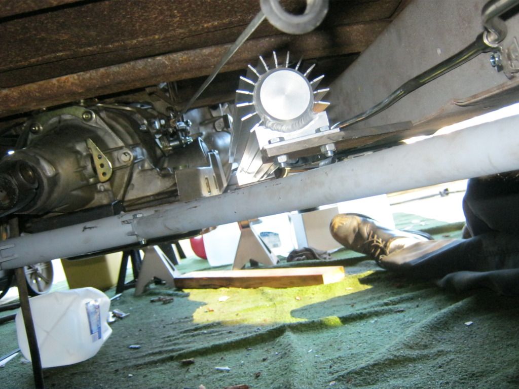
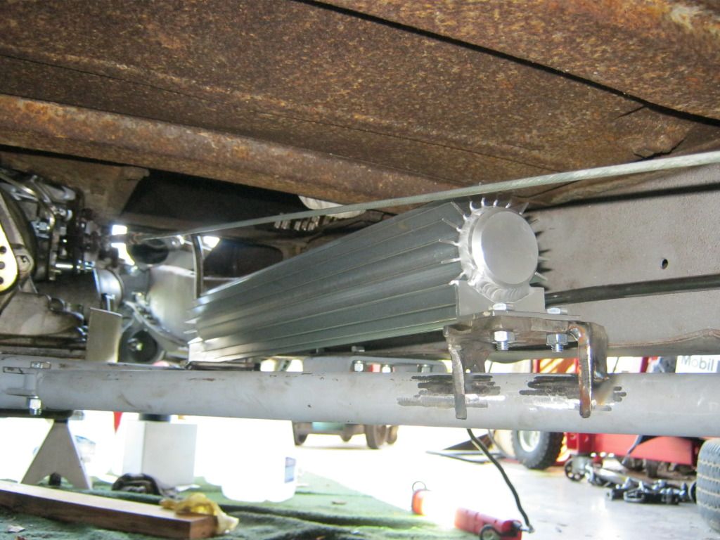
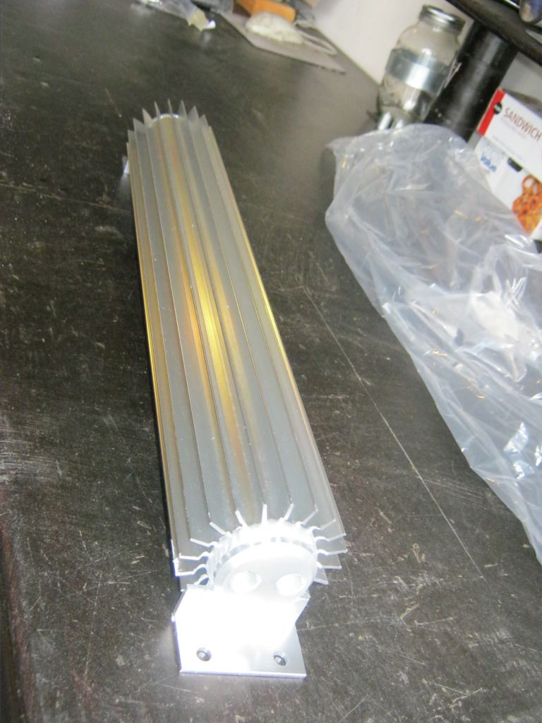
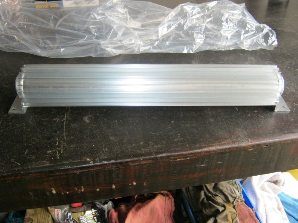
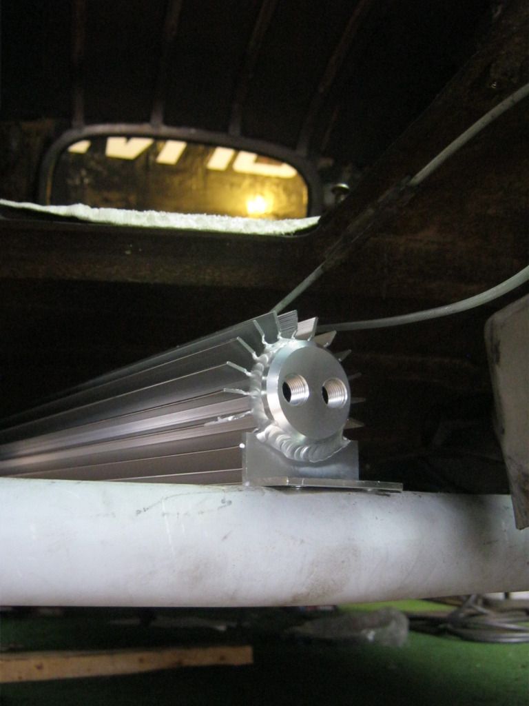
Bill suggested running an external transmission cooler to keep as much heat as possible out of the radiator.  Since he has been building hot rods and street rods for 50 years and I've been building them since March of this year, I thought I might take his advice.  This is a finned aluminum unit that I can mount anywhere I like and then run two steel braided lines with AN fittings from the transmission.  I plan to keep it close to the transmission so as to keep the lines short.  This will also be much easier than running hard transmission lines all the way up to the radiator through an engine compartment that will already be overcrowded.

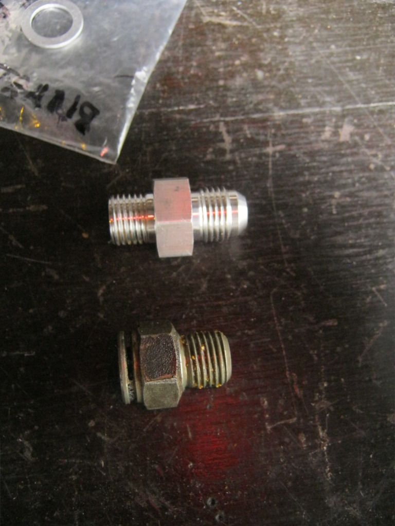
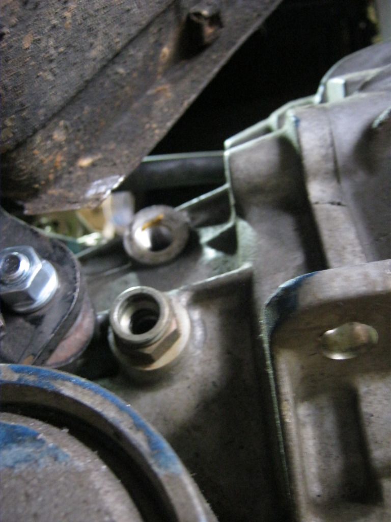
First I took the old fittings out of the transmission and replaced them with the new fittings.  I had to trim a little bit more of the floorboard so that the line will fit.  The top is the new fitting, the bottom is the original fitting.


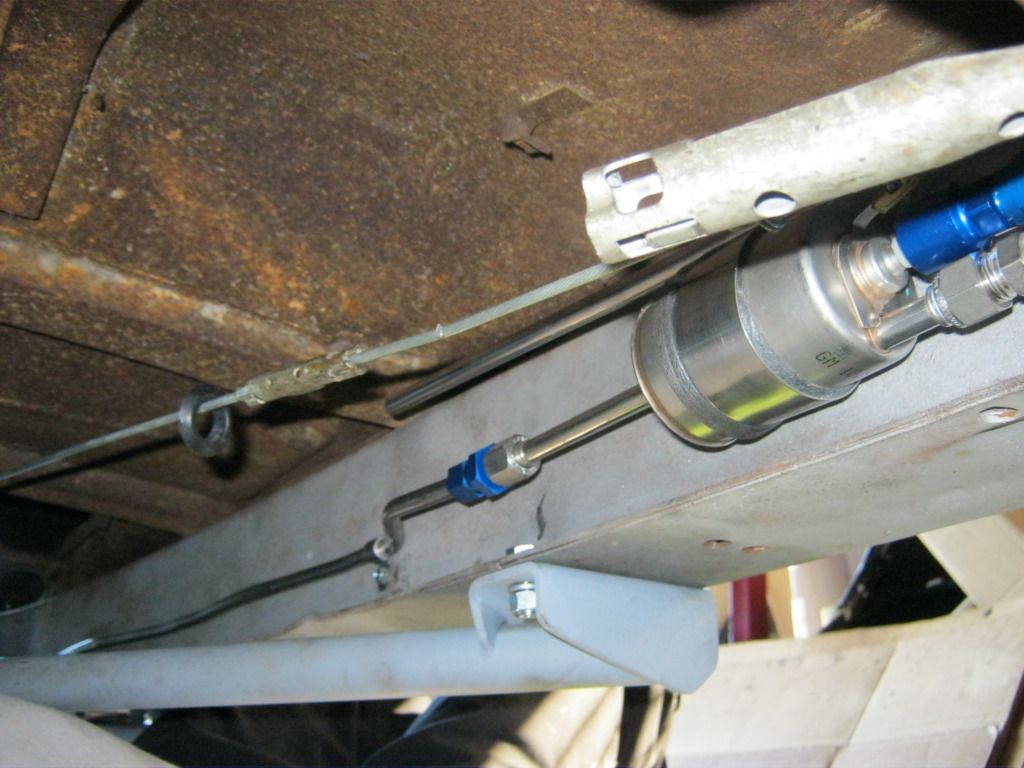
The cooler will mount somewhere here on the crossmember.  The problem is that I want to keep it as far away from the fuel line as possible to keep heat away, but I can't go too far because it will interfere with the parking brake cable.

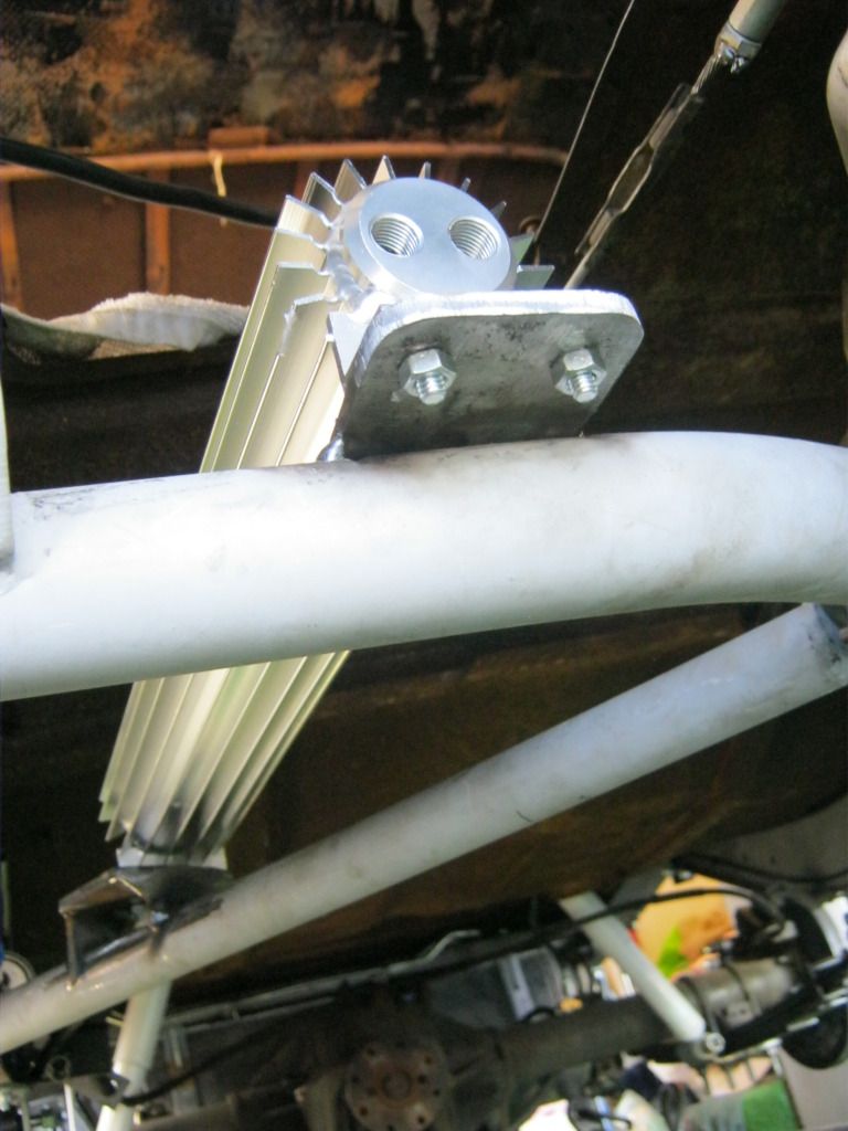
After doing a lot of mock up and taking measurements, I cut another piece of steel and welded it to the crossmember.  I did a bit more than tack weld it because I would be  putting quite a bit of stress on this piece while drilling the holes in the steel but I didn't weld it completely.  I was barely able to get the end of the welder in to get these small welds finished.  I'll complete the welds when I take the crossmember back out before I send it to be powder coated.

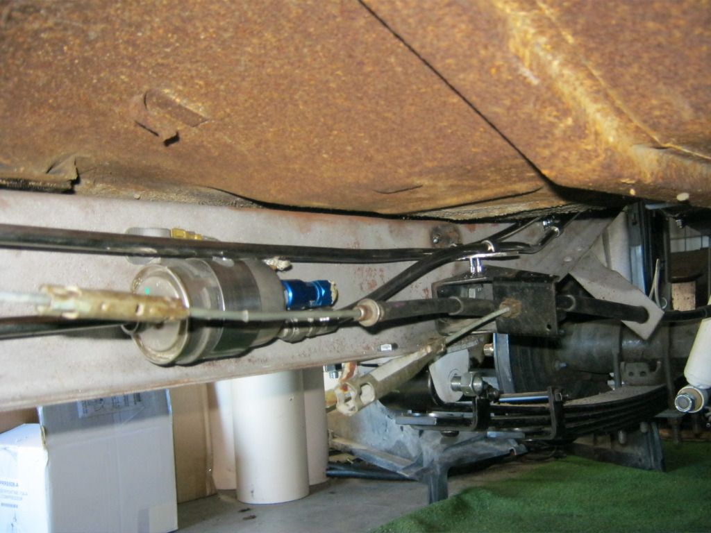
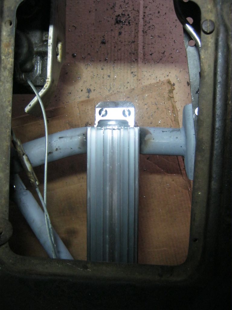
It will mount like this, under the floorboard where the battery used to be.

I got the rear mount cut and drilled but April called me in to dinner before I could mount it.  That will have to wait until next time.