Here's a picture I took of the first unit I have that came with my rear end. I had initially cut this one too short so I had to go back and get a second one, but this will work for my purpose here.
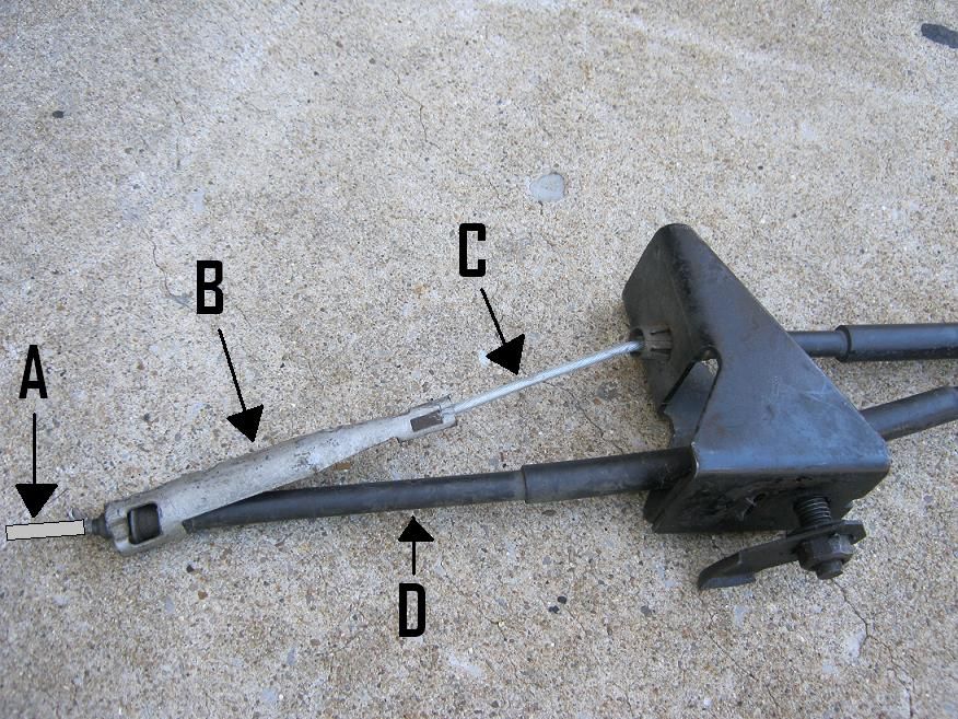
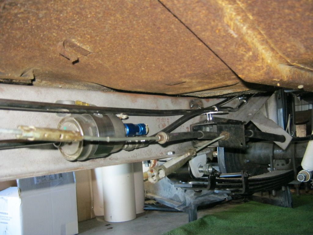
On the Explorer, the parking brake handle under the dash is connected to the cable (A). The cable moves inside of the rubber casing (D), but the rubber casing (D) does not move and is stationary. The cables (A) and (C) each run to their own respective side of the car for the two rear parking brakes, driver and passenger side. The cable (C) is attached to the back of the bracket (B) which is in turn attached to the front of the rubber casing (D). The problem is that the rubber casing (D) doesn't move, and since (B) and (C) are attached to it and the only way they can function is if they are pulled, there's no way for them to work. The cable (A) slides independently, inside the casing (D). After talking to various people and looking under an actual Ford Explorer, the only thing I can determine is that cable (A) and its casing (D) must have an exact amount of slack after the point which it contacts bracket (B) which will allow (D) to enter the bracket (B) at an angle, and bracket (B) must be pulled tight against cable (A), giving cable (C) tautness against where it is mounted by clips in the big black bracket shown. If this is true, when cable (A) is pulled it would then pull upon bracket (B) which would cause cable (C) to pull tight, but that is only given that once the slack is taken up in (D), it will allow both cables to pull at the same tension. Even though cable (A) is the same cable that runs through the casing (D), because it is mounted in bracket (B), this allows (A) to be held tight forward of bracket (B) but have slack after bracket (B). The only reason I can think of for this being the way it is is that if one brake froze it would still allow the other brake to partially engage, and that's only maybe, if my thinking is correct. I'm still not sure if the forces acting on each cable would be equal or if one engages before the other in a progressive style.
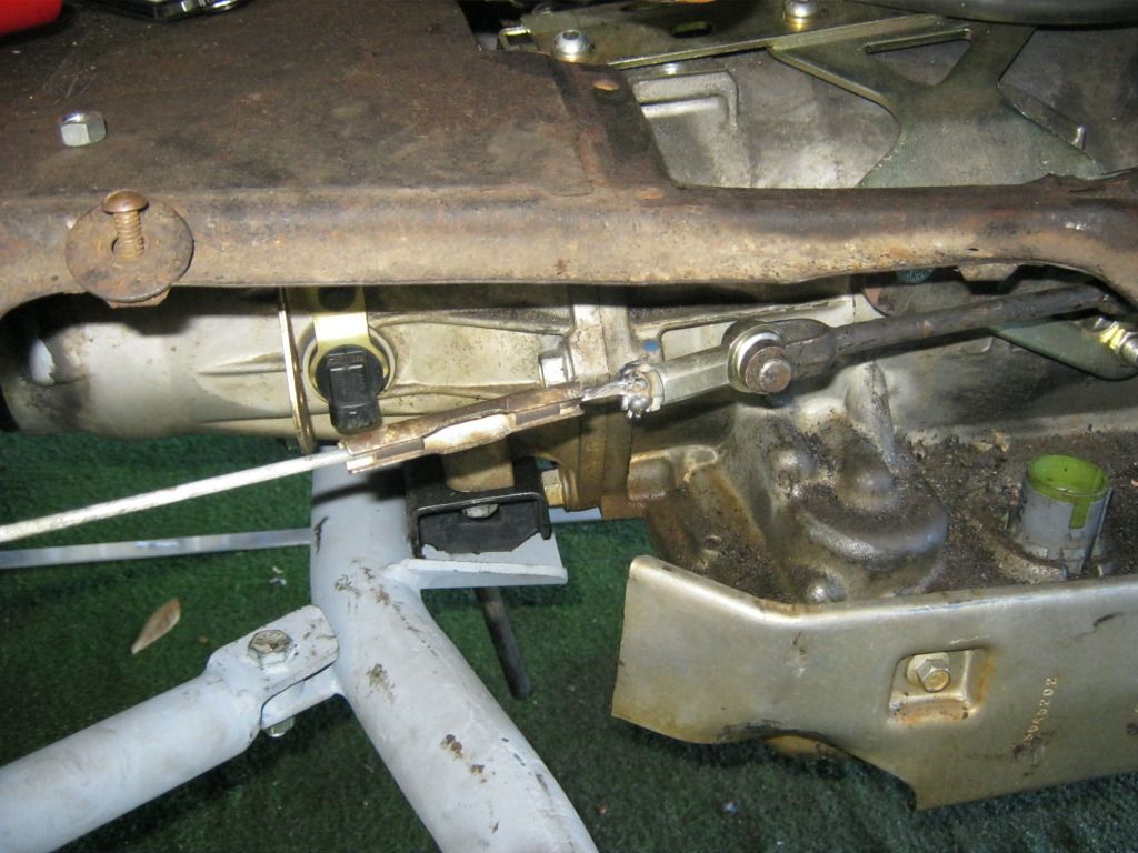
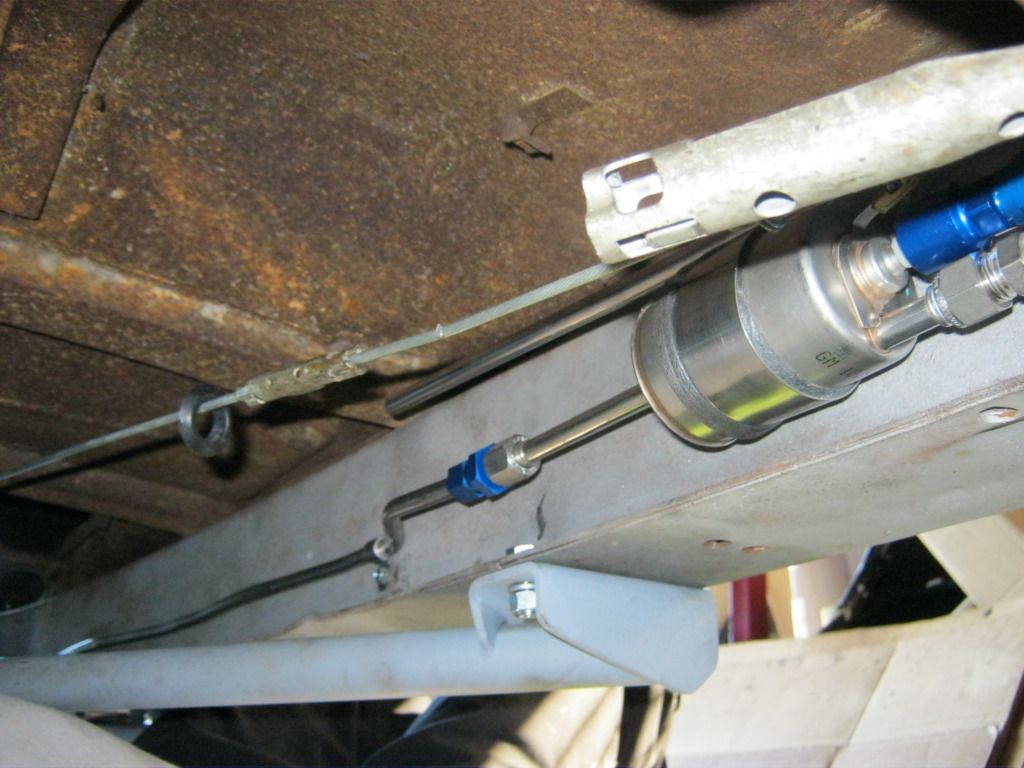
The problem I have is that I have already mounted the large black mount to the frame and there is no slack in my casing (D). There is slack is cable (C) and casing (D) is taught. This is backward to what I believe it should be. Moving the large black mount back would correct the problem, however the fuel lines have been run above the large black mount so it cannot be moved back to test this theory.
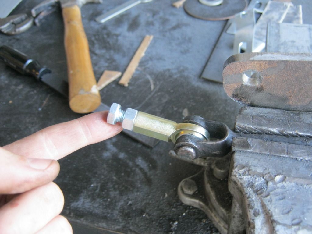
I have decided to wait until the body is back off so that I can better access this problem. My solution will end up being something like this: I am going to remove the bracket on the left in the picture below, that my finger is on. and replace it with a factory cable connection, like what is pictured on the cable to the right below the black casing, near where the black O-ring is visible. I will then cut the line on the right so that it matches the length of the newly extended cable on the left. The cable from the front will go back and mount in the center of a plate and each cable from the rear will extend through one side of the plate. When the parking brake handle is pulled it will then pull equally on each cable. This is how many emergency brake cables operate and is also how the expensive aftermarket cable made for this Ford 8.8 rear end is designed. What I do not like about the aftermarket design is there are no casings for the lines to run through so you must design pulleys or have the cables run a straight shot to your rear wheels. The casings on the factory setup allow me to run the cable far and out of the way and makes it much neater as well as frees up space that I'll be using for other things like a driveshaft, mufflers, exhaust, driveshaft safety ring and whatever else comes up between now and then.
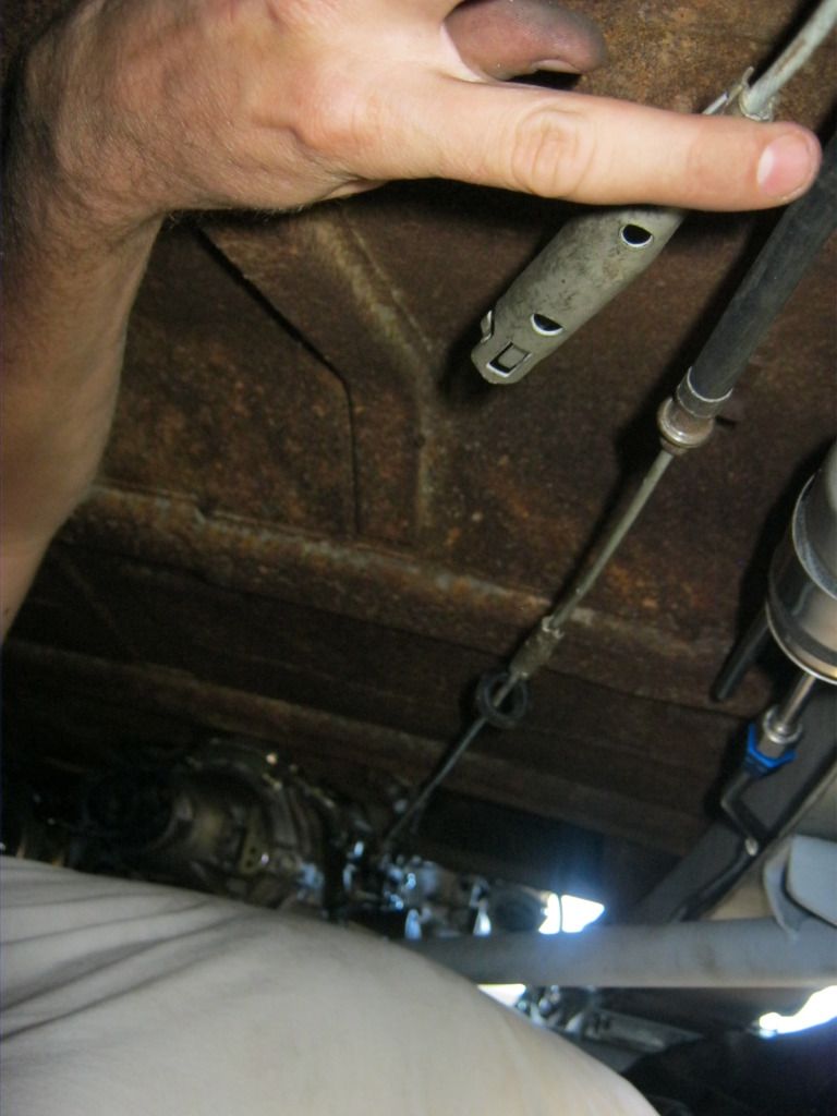
Here's a picture of how I connected the cable to the parking brake handle assembly. When it's taken back apart I'll finish the welding, but for now it holds enough for me to figure how how I'll set it all up.