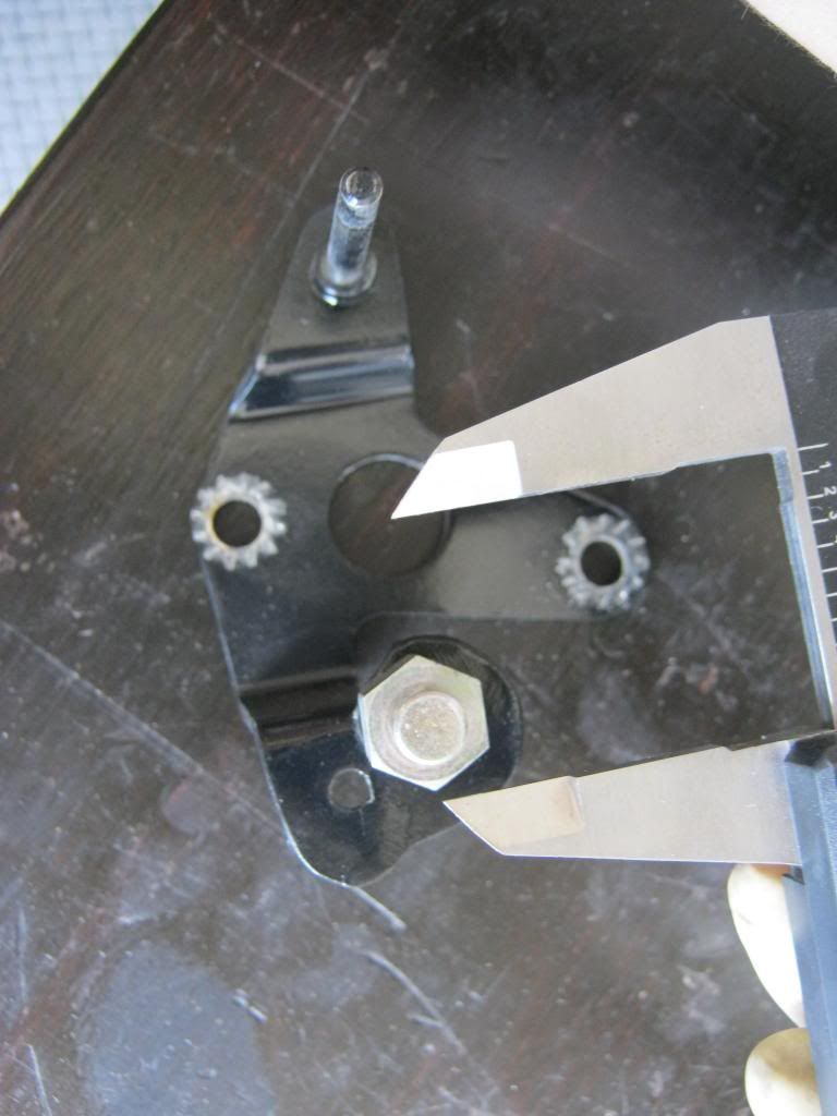
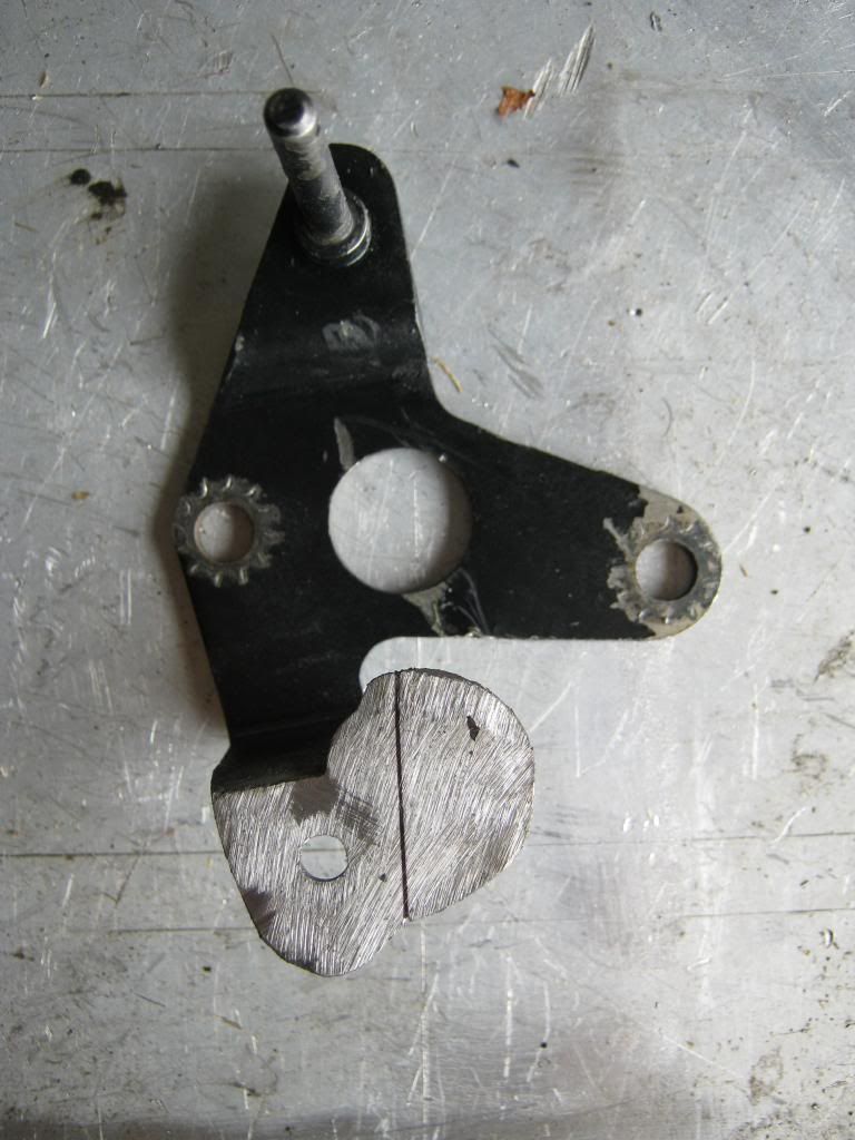
I welded up the old hole. Before I welded the old hole I taped the bracket to a piece of paper, found the exact center of the throttle shaft hole and drew a point on the piece of paper and then found the middle of the old TV stud hole and etched this line into the piece using the center of the two holes as reference. This line is my 23 degrees that I found earlier when I removed the carburetor the first time. I used a file to etch the ends of the line on the sides of the plate. I knew if I etched the top that when I ground down the plate after welding the old hole the etching would disappear. After I had the old hole welded and ground down I used the two scribe marks to redraw my 23 degree line. This would be my reference for where to drill the new hole.
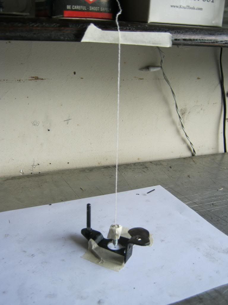
Because the two points I must measure between are on different planes it made it virtually impossible to get an accurate measurement by line of sight. Trying to look straight down was unreliable for providing precise results due to perspective issues. I had no tools that would provide me with a direct 90 degree angle for measuring. My solution was taping the plate to a piece of paper again and finding the exact center of the carburetor shaft hole. I then taped a string to the center of a pointed screw and made sure it hung straight. Then I taped the string to my desk and after making sure my desk had a perpendicular surface to the string allowed the point of the screw to hang as close as possible to the paper without dragging. I then knew that the string extended directly above my point and I could use it as a measuring reference.
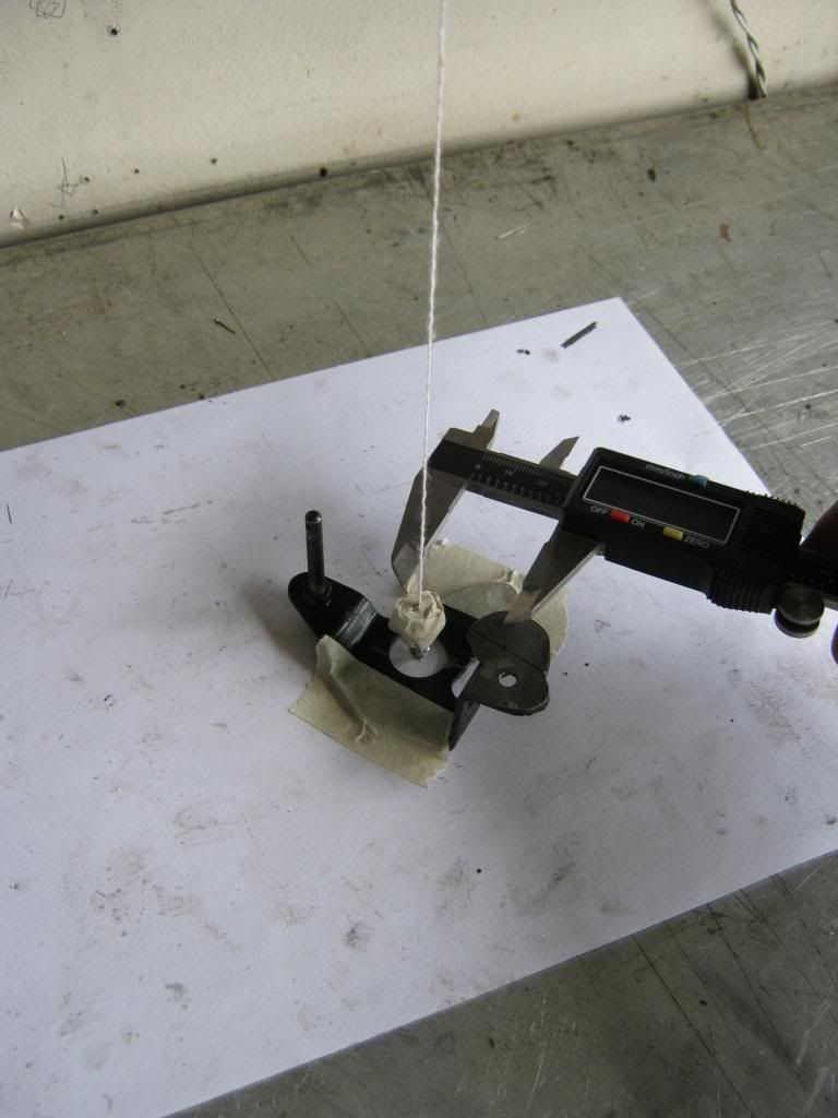
I used the caliper again and measured from the string along the 23 degree line. I made my mark, used a center punch and then drilled the new hole, followed by a new coat of primer and paint. I measured the end result and it was correct. Finally I could rest easy knowing my custom TV stud was exactly right.
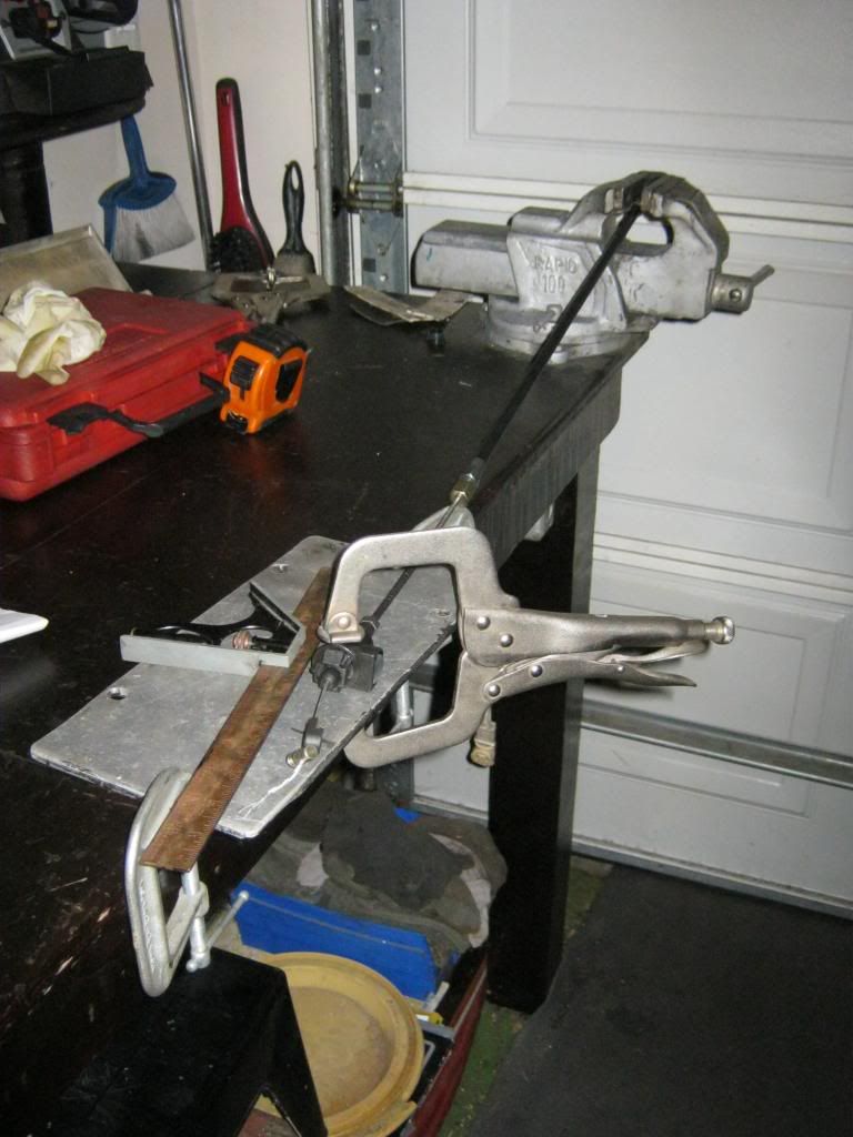
Now moving on to the bane of my existence for the last two weeks: The TV cable. When I installed my new TV cable, it too did not ratchet. With great effort I attempted to adjust the cable time and time again. It still would not ratchet or adjust exactly right. The transmission also will not go into 4th gear (overdrive) which may or may not be related to this problem. I have learned that it is common for a rebuilt 700r4 to have some difficulty making its first 3rd to 4th shift. This cable caused me immense frustration. It was the very last thing standing between me and the car being completely drivable. I spent many, many hours trying to research again and again how the various styles of TV cables work, how the throttle valve itself functions and how to adjust a cable properly. I tried to find others that had difficulty with the TV cable. I only found a couple instances of others with the same problem but unfortunately it seems they never resolved the issue to my satisfaction. I became utterly frustrated with the fact that the company sells this item and time and time again I would follow the instructions and it would not function properly. It seemed as though the ratcheting mechanism had no connection to the cable that slides inside of it. April noticed that I would often be sitting and staring at nothing, lost in my mind, going over and over again in my head the construction of the cable to try to figure it out. Tonight I was in the garage and mounted the TV cable to my table to represent how it is mounted in the car and began taking measurements.
At long, long last I finally figured out the problem. Though the directions the company sent were not technically wrong, they completely left out at least two crucial steps and equally as many vitally important warning notes. I am going to do the best I can to describe the situation, but it is complex, particularly without having the actual cable as reference and without a previous basic understanding of how a 700R4 operates. I have made a series of drawings to attempt to demonstrate the problem and solution.
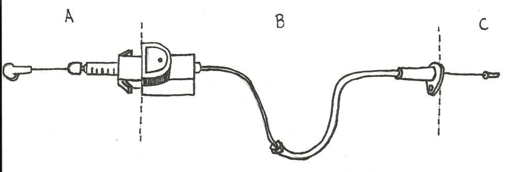
The drawing below represents the TV cable. Measurement A is the portion of the cable that goes from the carburetor to the ratcheting adjustment mount. Measurement B is the portion that goes from the adjustment mount to the transmission. Measurement C is the portion of the cable that is inside the transmission and connects to a valve which, when pulled, allows fluid to flow inside the transmission for proper operation. The dotted lines indicate the two points where the cable is mounted to the car. The A-B point is mounted to the manifold, the B-C point is mounted down on the transmission.
The cable is meant to be pulled and pushed. If you imagine pulling this line at the end of measurement A it is easy to see that it would cause the line to pull away from measurement C. Imagine now that we need extra length for measurement A because it is not long enough to fit onto our carburetor. The problem is that if you pull on the cable to get extra length at measurement A you naturally shorten the length of measurement C. This causes a problem because no matter what we do measurement C (the distance the cable is in the transmission) must always remain the same. Remember that measurement C represents the amount of line inside the transmission that pulls on a throttle valve. Lets say this valve has 2 inches of travel. This means that our measurement C must always be 2 inches. How can we possibly add any length to measurement A without taking away anything from measurement C?
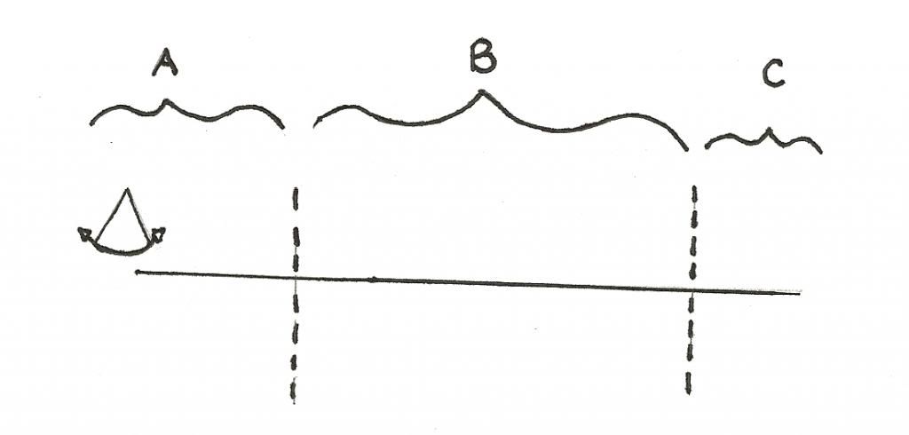
The answer lies in the fact that the length of measurement B does not matter. As long as you have enough to connect measurement A to measurement B, then you are OK. You can add as much as you like to measurement B and still be fine. Notice the arc drawn at the end of the cable in measurement A? In our drawing, the left side of the arc would represent the throttle plate moving to full throttle. Notice our cable does not reach the end of the arc? We need to add distance to measurement A without taking any away from measurement C. The solution is to add slack, or extra cable, to measurement B.
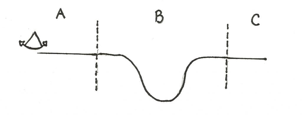
In the drawing below, if you imagine pushing the line from measurement A you must imagine that the line will follow the same U-shaped path I have drawn. In reality if you pushed on a wire like the one I have drawn below it would just bunch up in measurement B and would not push on measurement C, but for now, just imagine that when measurement A is pushed the cable follows the shape it is in, and just like when the line was straight, any amount you push on A effects C. By adding or removing the slack in measurement B you can add or remove that slack to measurement A. We have transferred some of the extra slack from B and added it to measurement A but the overall length of the cable has remained exactly the same. This means that even though A has "grown" and B has "shrunk" C is not effected in any way. So A is now longer and has more length, yet if I push the wire at the end of A in 2 inches it still only pushes C out 2 inches. Because A is longer it means I can now have a enough cable to reach the end of the arc, and if you remember the arc represents the distance the cable has to travel when attached to the throttle shaft, because we all know that the throttle shaft travels in a circle and part of a circle is an arc.
The arc in the picture above represents the travel my TV stud has while mounted on the throttle plate. When the gas is pushed, the throttle plate on the carb turns and causes the TV stud to move from the right side of the arc (idle) to the left side of the arc (full throttle). Lets pretend that the distance between idle and full throttle for my TV stud is 2 inches (this would be represented by the pie-shaped arc I have drawn in the picture above), but lets say I have a cable that can only reach 1 inch. Since measurement B has an excess of cable we can borrow an inch from B and add it to A, which then lets our cable extend all the way out and reach the TV stud when it is at full throttle, which is 2 inches away from where it was at idle.
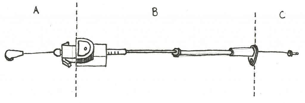
That's all fine for an imaginary cable but how do we mount it on the car? We need a sheath for the cable to slide inside of. We need a way to add and subtract distance from B and give or take it from A as we need, all while keeping C the same. We do this by adding a ratcheting mechanism between A and B. The drawing below represents what the cable looks like, but this drawing has a problem. There is no extra distance for B.
So, if you add or remove sheath (which also adds or removes cable) you are effecting the overall distance that A can reach, however this does not effect the distance C is pulled. It still remains the same. What if you do want to effect C? Since the end of C is connected to the throttle valve in the transmission, what if you want the throttle valve a little more open at idle? In this case, on a universal TV cable, you would loosen the clamp at the end of the TV stud clip and only pull on the cable, not the sheath. So, adjusting the cable only adjusts where the cable is at idle, adjust the ratchet (or sheath) adjusts where the cable is at full throttle.
So what was my problem? The extra distance needed in measurement B was not mentioned at all in the directions so when I installed my cable it looked like the first TV cable drawing, tight with no extra slack. Since there was no slack there was no extra length to allow the sheath to ratchet forward. Also, the nut on the sheath in measurement B must be tightened before the TV cable is adjusted at the carb. If not, when the ratchet is pulled it will not pull the sheath as a whole. It will just pull more sheath out from inside of the bigger sheath and add more distance to B, which doesn't do any good when you need to add it to A. When I set my cable up I of course routed it as cleanly as possible without any extra cable lying around. That meant when I tried to ratchet the sheath there was no extra line or sheath left to pull out. The first TV cable drawing is how I had my cable mounted at first. The second drawing is how it should be mounted.
A couple more things not mentioned. Before adjustments are made you are supposed to push the sheath fully inside the ratchet mechanism, toward the transmission and away from the carb. Then when you push the throttle to full throttle it will automatically pull on the cable and add as much is needed to let the cable reach full throttle. What they don't tell you is that this is wrong. If you push the sheath all the way, completely in the ratchet mechanism as far as it will go, it messes with the ratchet system and it will not extend. There is a square shape portion of the shaft on the ratchet that extends into measurement A. You must line the flat part of this shaft with the face of the mechanism for it to work. If it is pushed in further than this it will not work.
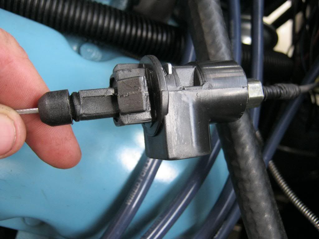
The picture below may explain what I mean more clearly. This is the ratchet mechanism. It cannot be pushed in without the "D" shaped button being depressed, however it can be pulled out without the button. This is how it auto-adjusts. When pushing the shaft inside the housing you must not push it up to the very back of the round head on the end. You must only go to the point where you can see the flat surface, which in this picture appears to be about 2 mm to the right of the round head.
Also, something not mentioned in the instructions is that once you tighten the nut that determines the length of the sheath from measurement B it cannot be adjusted again. There is a compression fitting inside and this can only happen once.
To sum up how the system works, when you push or pull the wire the ratchet system allows travel to be taken from measurement B and added to A as needed, so the overall travel of the entire cable stays the same and the change in distance only happens between A and B.