I contacted a company called Mike's Carburetors about finding a rebuild kit for Woodson's '56 Chevrolet carburetor. As it turns out the actual name of this type of carburetor is 2 Jet. These carbs came with a tab held on with one of the top screws that had all the identification numbers stamped into it. If it is missing there's no definitive way to identify what carb it is. These carbs were used for so long on so many different types of vehicles and they are all so similar over the slight variances that it is very common that they are not found on the type of engine they came with. Another way to identify these carbs, as far as what rebuild kit to use, is by the accelerator pump. The tab was missing from this carb and the accelerator pump was broken and incorrect so I sent a few emails with Mike himself and we determined the best guess as to what kit to order. I also had to do the same with two replacement idle mixture screws, which have no identifiable numbers and must be matched with measurements.
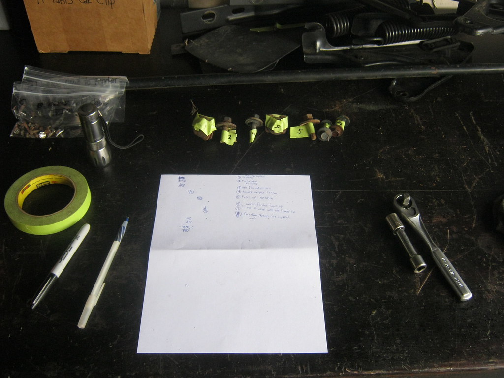
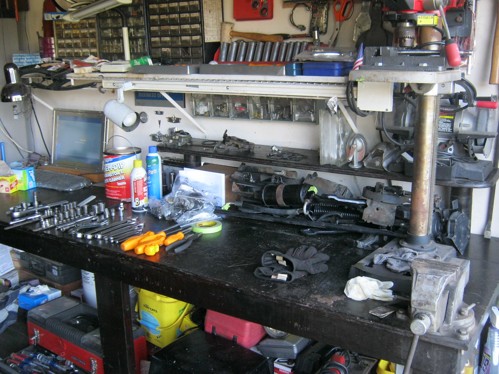
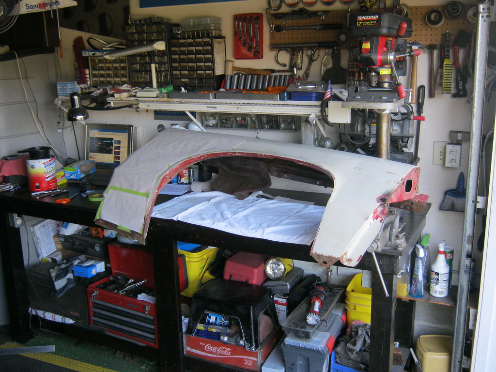
After getting everything clean I had a mess of parts. Fortunately I took a lot of pictures and put them on the computer on the desk so I can reference them.
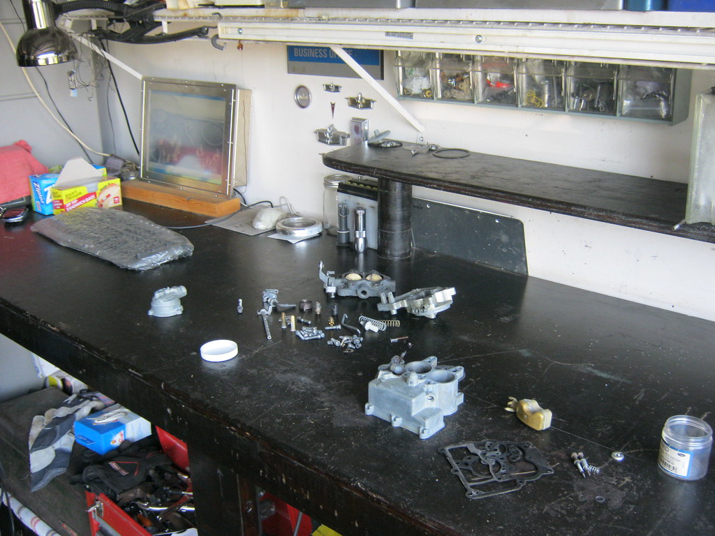
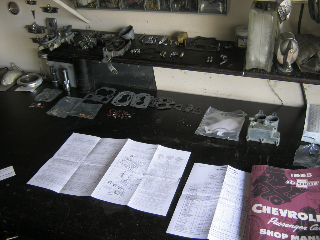
With the aid of the pictures I finally got everything sorted out. I laid out the new kit and replaced what was similar.
I like to take a wire and clean out as many of the fuel and air passages as possible, even after chemical cleaning and blowing them out with compressed air. I couldn't find my wire so I ended up stealing the twist-tie from the bread in the kitchen and taking the plastic coating off. I put the bread in a big zip lock bag so it wouldn't go stale and to keep April happy.
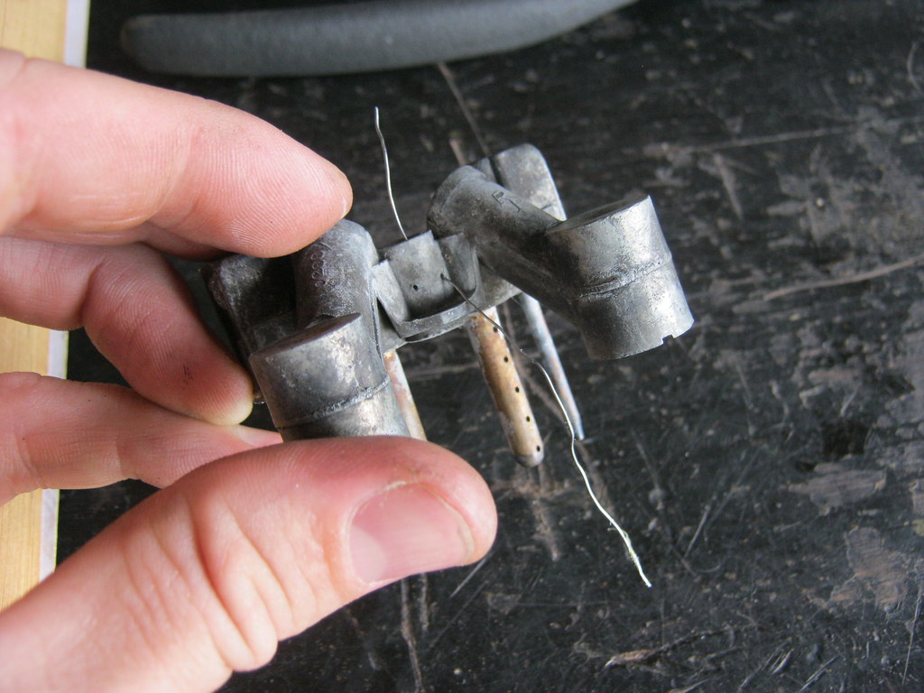
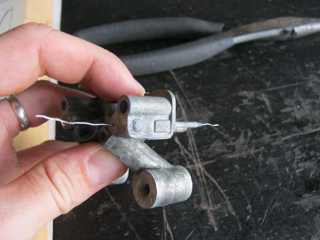
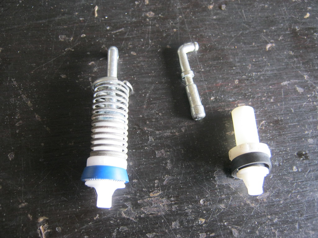
The car had suffered from a terrible hesitation when accelerating. I would say this is why. The old accelerator pump on the right was in two pieces. They did not appear to have ever even fit together, as the shaft that is supposed to fit down into the white plunger was too big in diameter to fit. The new one on the left is how it is supposed to look.
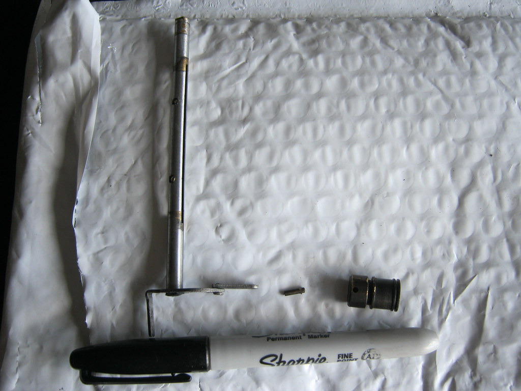
As I was reassembling everything I found a small piece that I couldn't identify. I soon realized it was the piston from the choke cylinder. I didn't remember it because it had been attached to the end of the choke shaft and I hadn't paid specific attention to what it looked like. That is when I realized the minute pin that holds the piston to the shaft was missing. Fortunately, after digging in the bottom of the carb cleaner can with my hands I found it in the bottom. It was so small that when it came loose from the piston it fell through the tiny holes in the tray that is in the carb cleaner can.
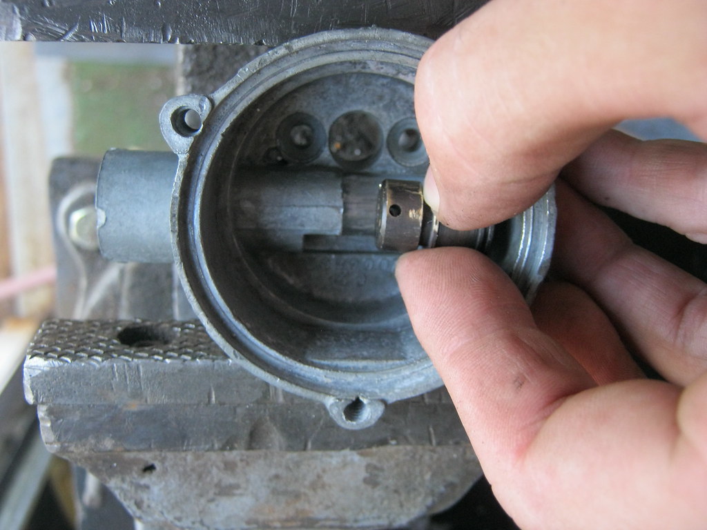
One issue with the car is the choke never functioned at all. When I went to install the choke piston back in the cylinder I found out why. The piston would not go into the cylinder without extensive force. It and the cylinder had burrs on them. I took a fine file and filed the piston until the edges where smooth and uniform.
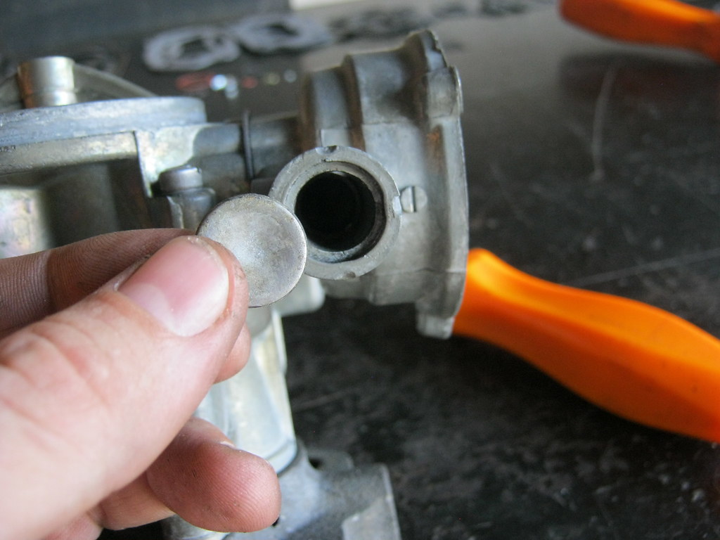
To access the cylinder I had to remove this press-in plate at the bottom. It was a challenge to find a way to remove it, but I finally stacked two bolts on top of one another inside the cylinder and used a T-shaped chisel to pry it out from the inside. The original idea may have been to drill it out, but I didn't have another one so I had to make sure I didn't damage this one while removing it.
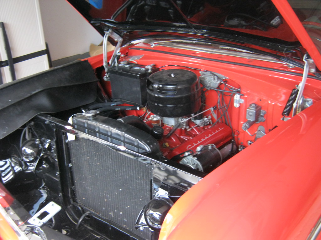
I cleaned the top of the manifold, installed the new gasket and hooked up everything else. I poured a little gas into the top of the carb and it fired up almost immediately. The choke pulled off as it should and there was no hesitation in it at all, even when holding the brake and punching the accelerator. I'm going to go back in the future and siphon out the remainder of the ethanol gasoline and replace it with nonethanol gas. I also want to see how it starts while the engine is cold without the aid of pouring gasoline in the carb.
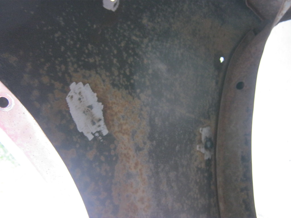
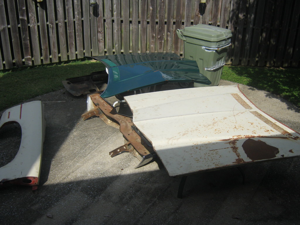
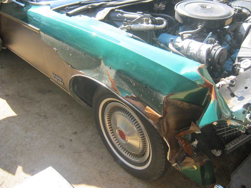
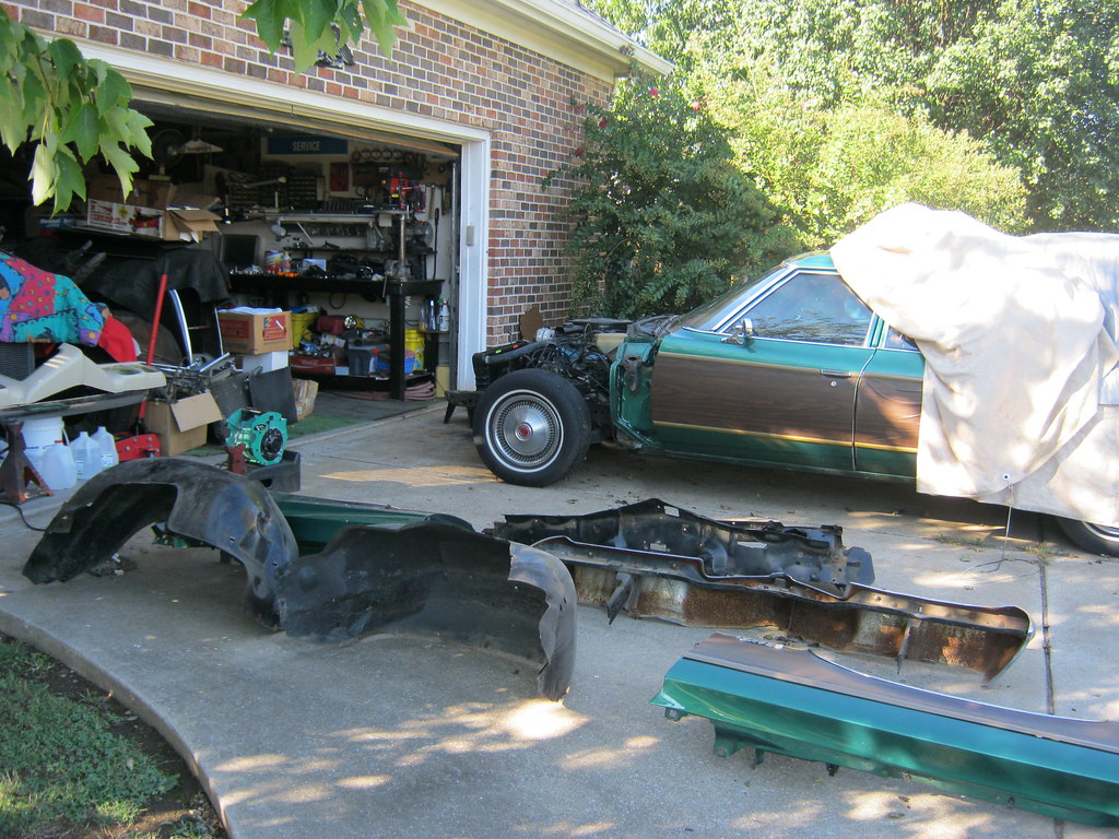
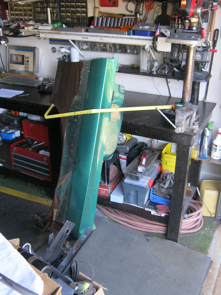
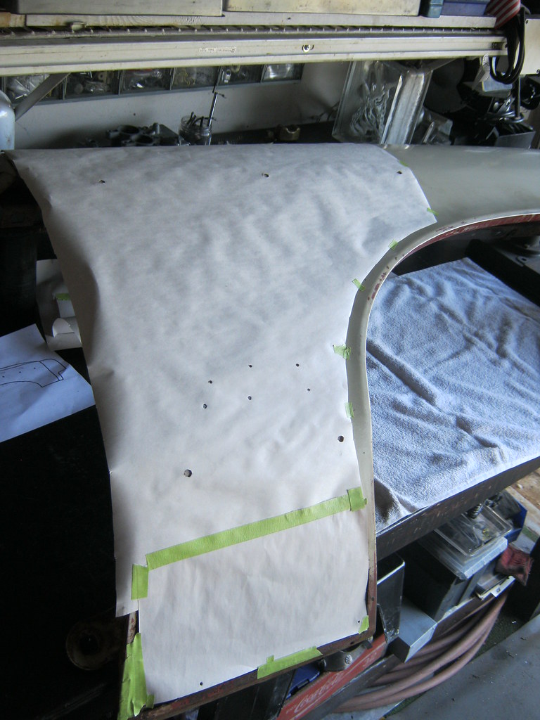
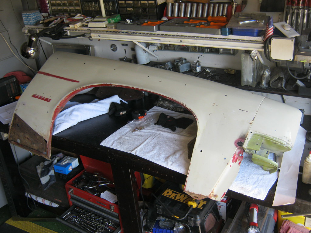
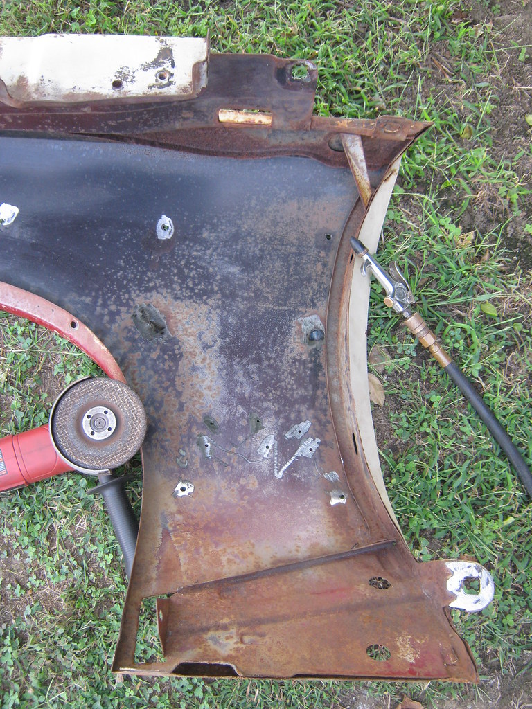
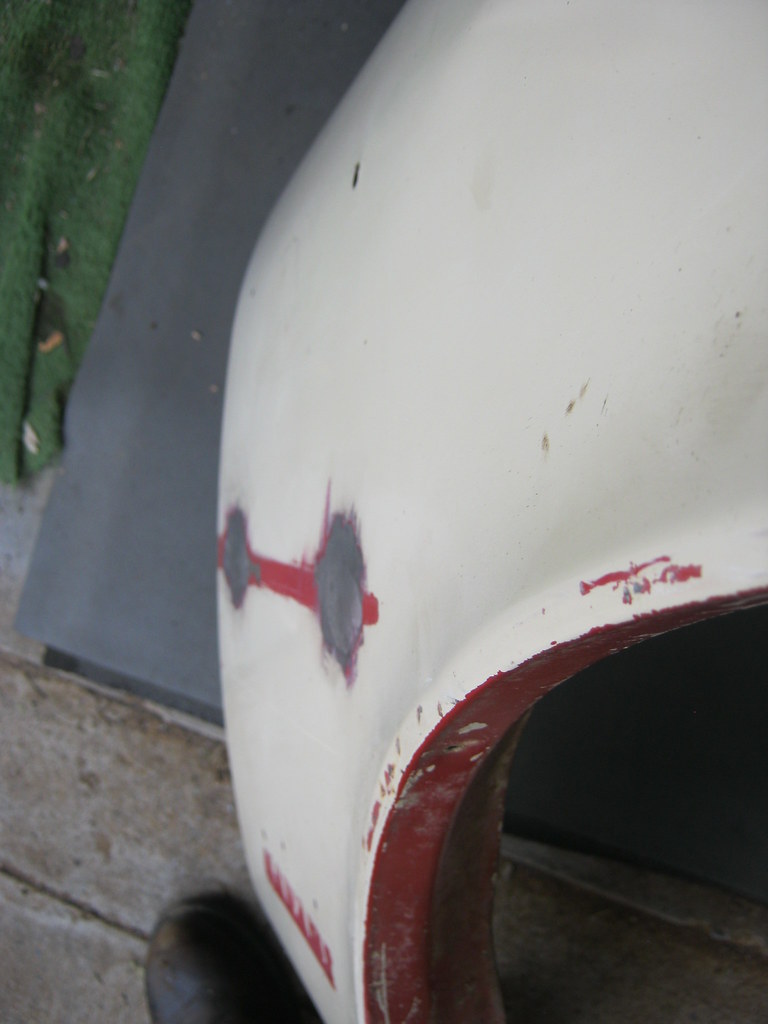
The next step for The Clam is to get the new passenger fender in shape to send to the sand blaster. I want to get all the unneeded holes welded shut and the new holes drilled before taking it to the sand blaster. This means measuring all the holes in the old fender to transfer them to the new one. I was able to use the back half of the old fender for measurements, but had to use the driver side fender for measurements for the front of the fender because the old passenger fender is all crunched on the front. I found that a metal tape measure did not bend sufficiently to measure around some of the curves on the fender and holding it myself was a challenge.
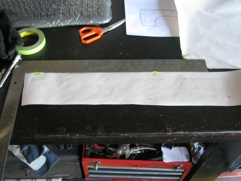
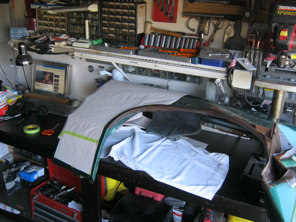
I used some of the newspaper end rolls I got years ago, cut out strips and used the straight edge to measure distances, which I marked with a pencil, using the crown of the fender as a reference point. Fortunately on this car this body line is very sharp and pronounced so it is easy to get an exact reference. Some fenders have a more rounded, gradual bend and finding the top can be more subjective depending on the lighting.
Then I measured those markings on the table with rulers and tape measures
Then I transferred all those measurements to paper. In the same way that a copy of a copy
gets worse and worse, a very slight variation in a measured spot can
produce inaccuracy if you attempt to take your next
measurement from where you just measured to, and by the third or
fourth time you do this you can be very, very far off. Because
of this, I try to measure the distance to the center of all holes
from one original location.
I also copied two diagrams from the Fisher Body Manual that shows all the pieces of woodgrain. I scanned them and put them together on one sheet. This will allow me to identify each piece and label it when I remove it so figuring out where they all go won't be the huge hassle it was last time. I'll have to wait to locate and drill the bottom rocker panel bracket holes after I've welded in the new patch panel, which will be after the fender returns from the sandblaster.
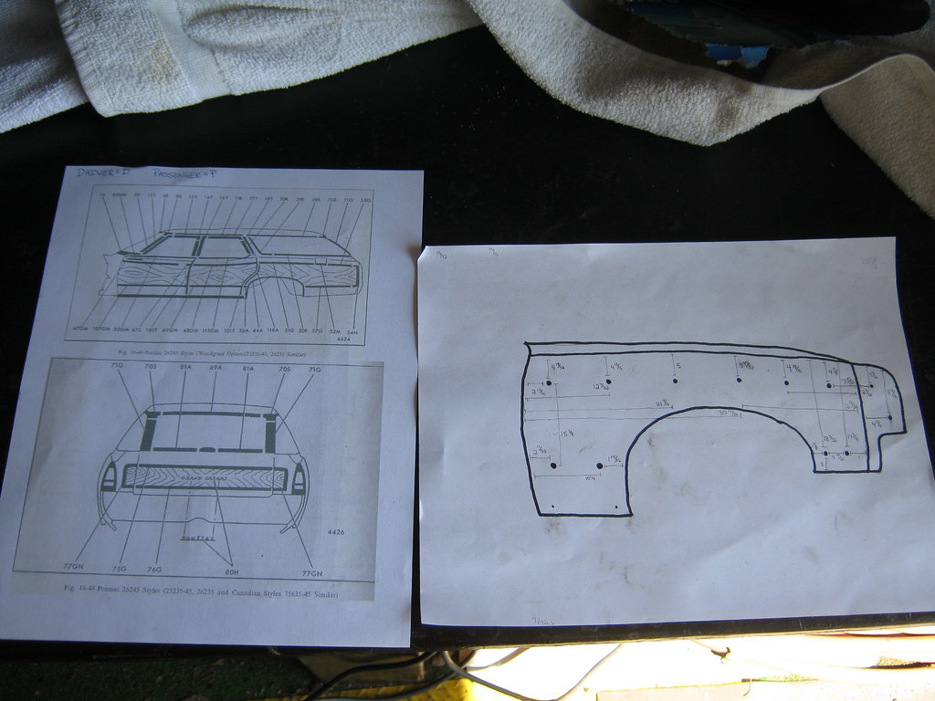
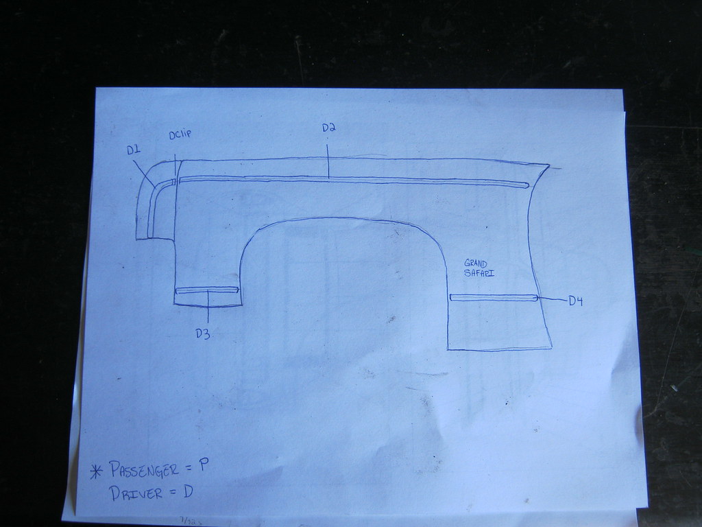
For some reason the Fisher Manual didn't include diagrams of the front fender so I had to make my own on the back.
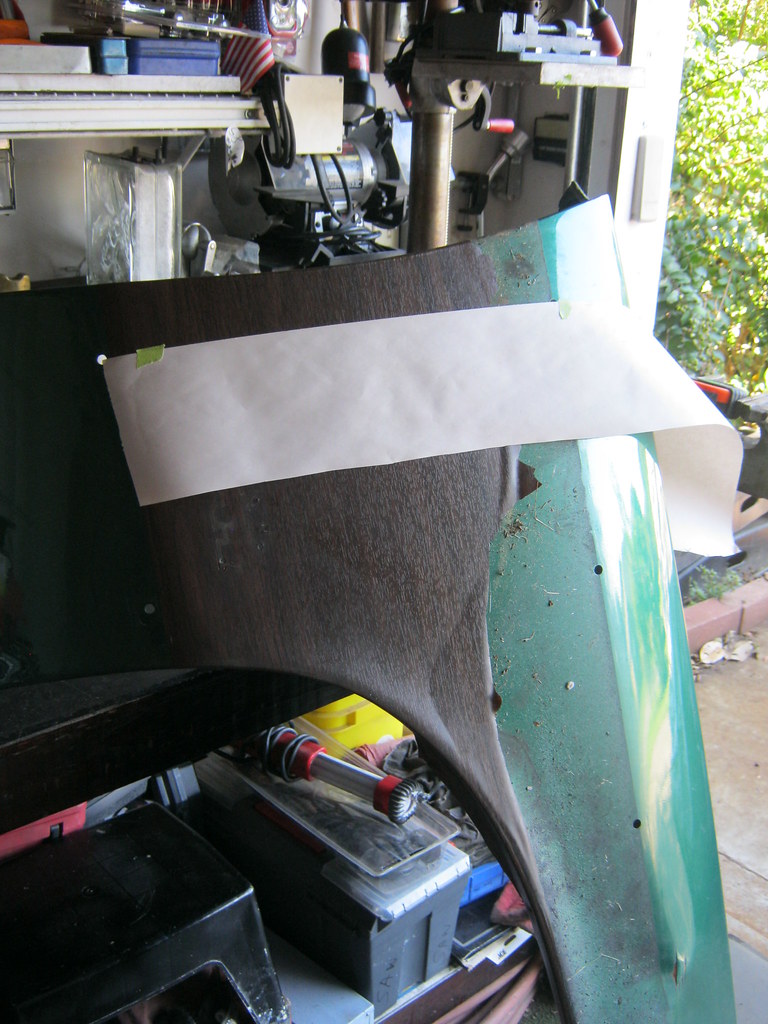
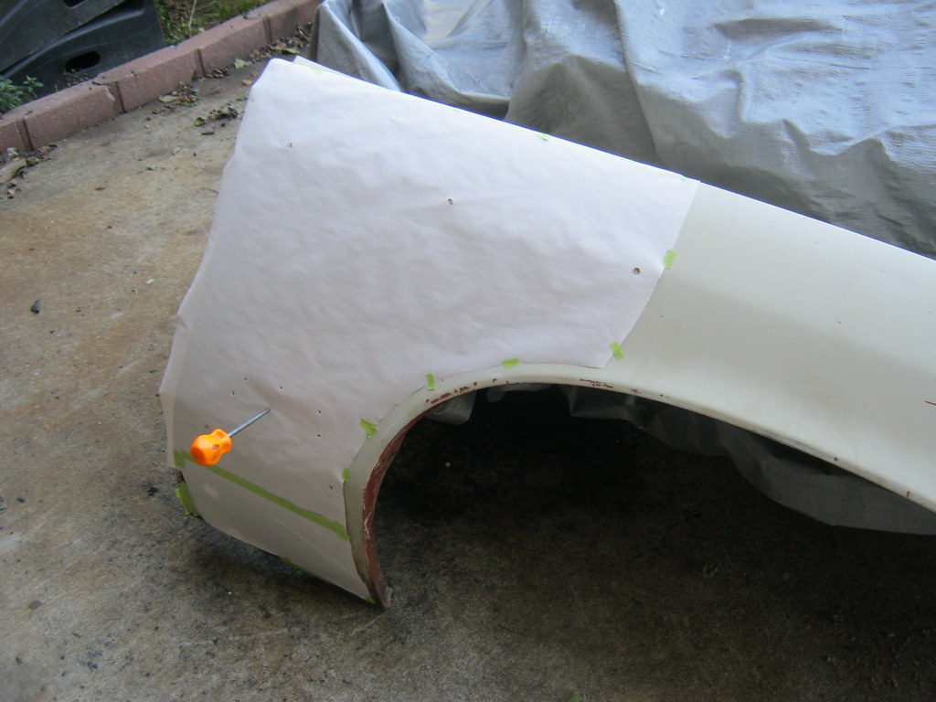
I used a few different methods to take redundant measurements. One way was to create a template of the old fender using newspaper endroll. I had to use more than a single sheet so that the paper would lay flat over the compound curves of the fender.
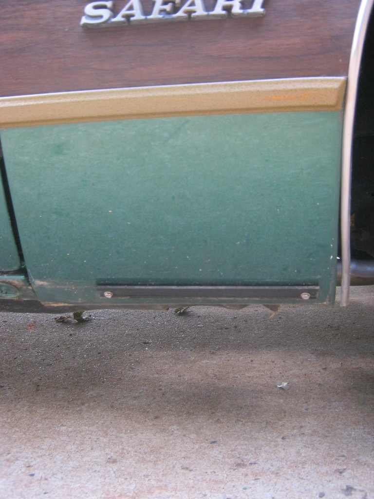
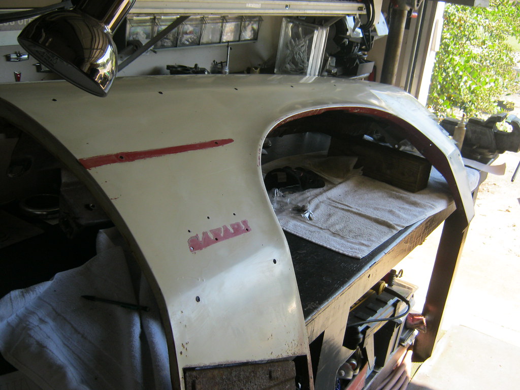
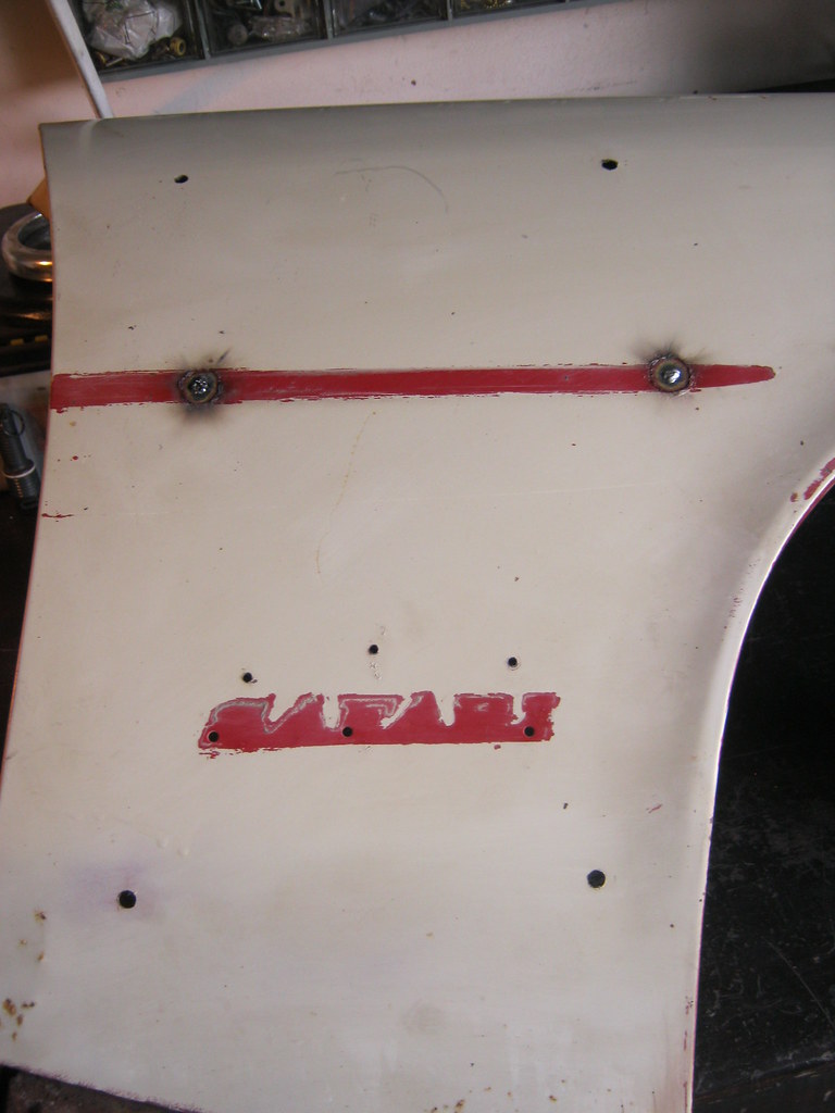
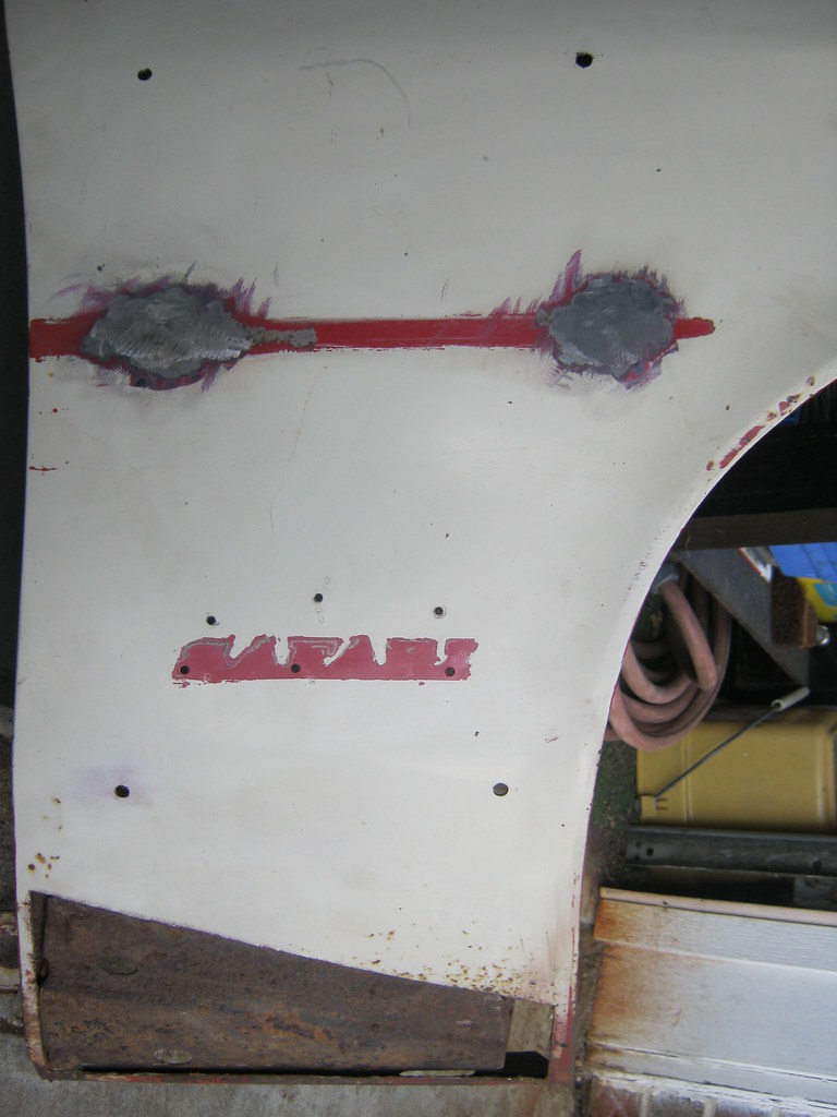
One thing I was not looking forward to is welding all the side script emblem holes closed and relocating new ones. Without holes to put the emblems into, the emblems will stand about 2 inches away from the mounting surface, which makes it very hard to line up straight when trying to locate new holes to drill. Also, the mounting studs are staggered, rather than in a straight line, compounding the problem further. After looking I noticed that it appeared that the Pontiac designers had simply kept the SAFARI emblem in the same space and simply mounted the GRAND emblem over it. I had assumed that they would have lowered the Safari emblem to accommodate the spacing of the extra GRAND emblem, but I was happily wrong. I measured to make sure and confirmed the holes were in the same place. This meant that I could take a piece of cardboard, put it on the backside of the old fender, trace the holes with a pencil and then transfer that perfect spacing and alignment to the new fender, which saved a lot of work and time. I used this cardboard method as well as the paper template to double check that everything was where it should be.
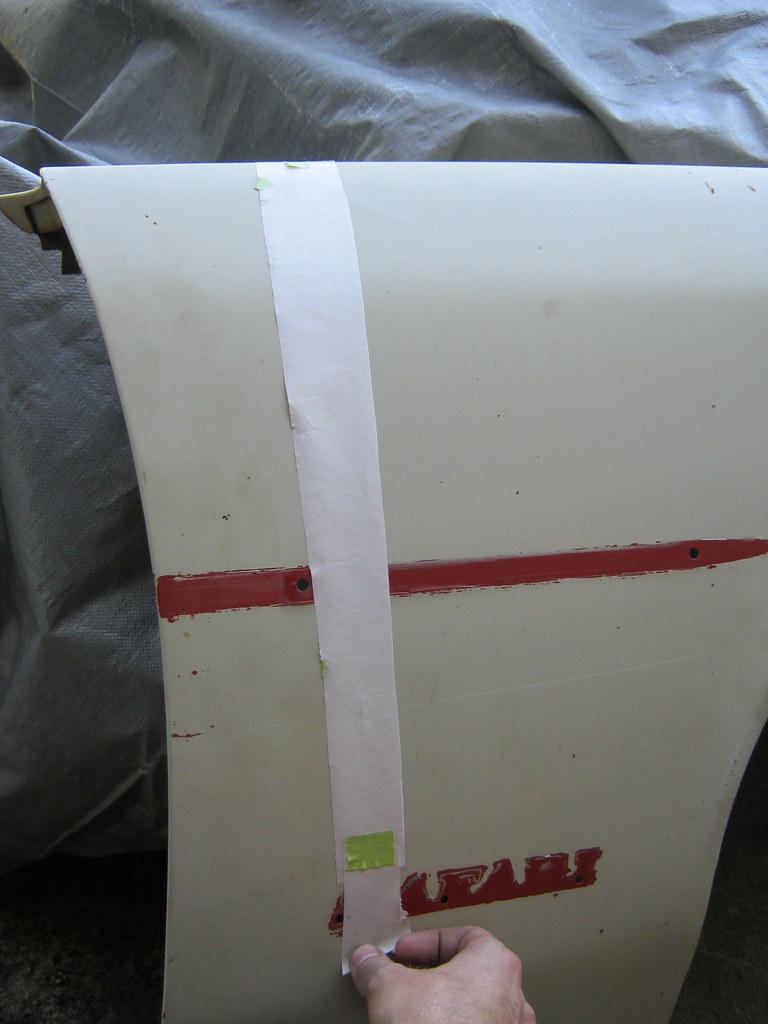
I transferred the template from the old fender over to the new fender using the very top, rear corner and the top body line in the fender as a reference point
When I tested to see if my template was accurate I found all three of the SAFARI emblem holes aligned perfectly.
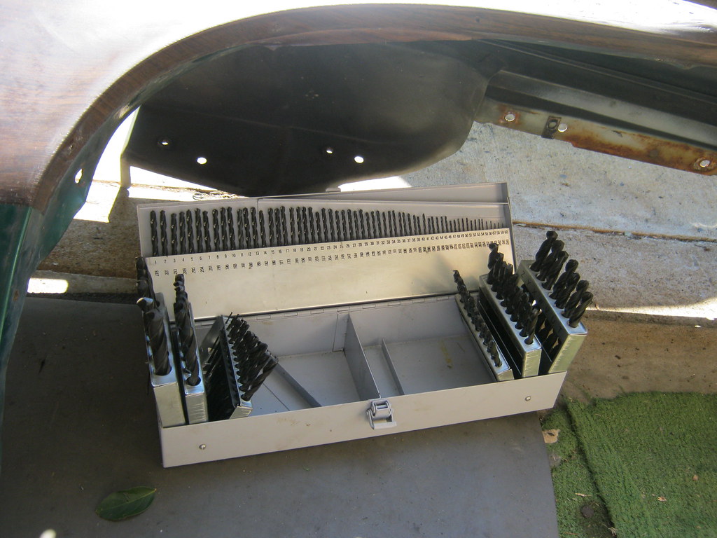
Fortunately, at an estate sale a while back, I obtained a much more robust selection of drill bits. This allowed me to match the size of all the holes perfectly. As a side not, this will also allow me to drill slightly undersized holes which are used in taping threads to the correct size.
After marking all the holes I removed the template and put a dot in the center of all the holes I had drawn and then triple checked the alignment of all the holes with the various measurements I'd taken.
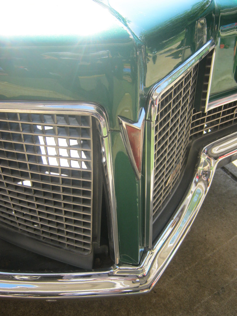
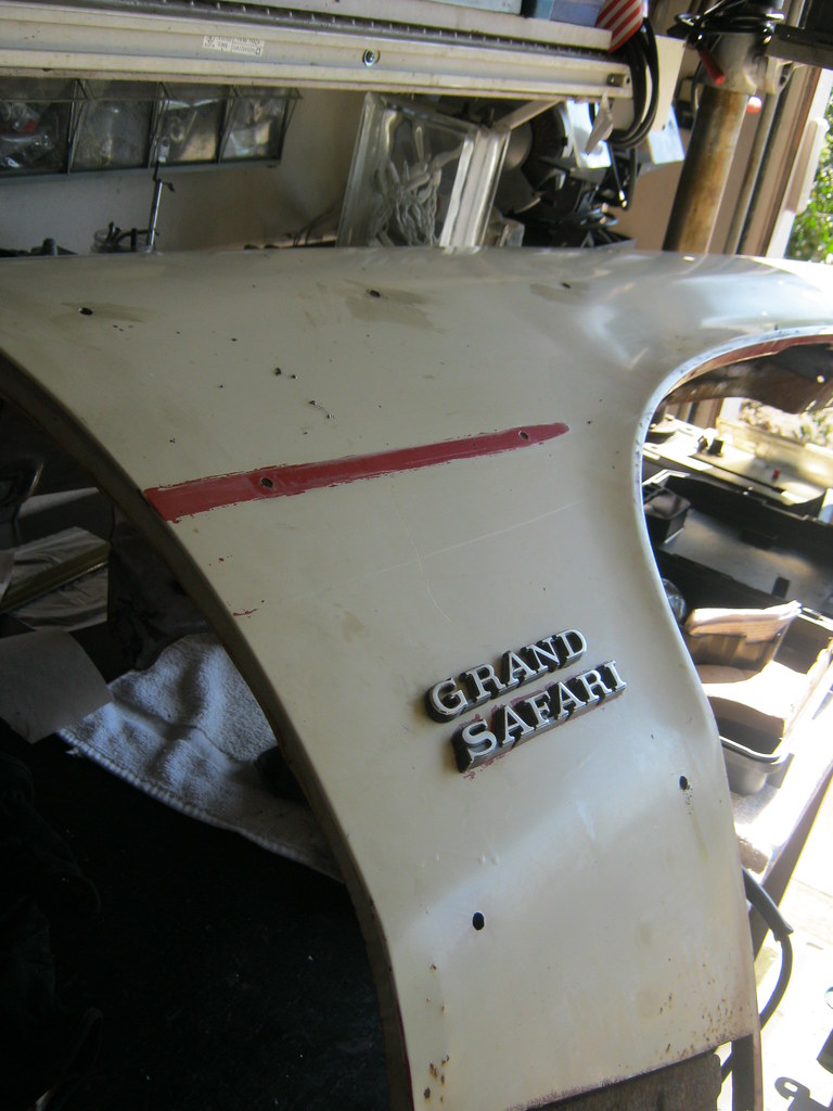
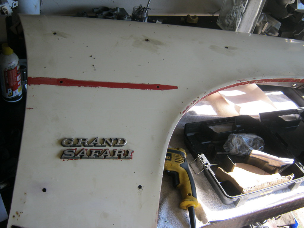
The emblems turned out great. The only difference is that the holes for the SAFARI emblem on the new fender were very slightly larger than the old holes so the emblem has a small amount of play. This may cause it to look a bit off here, but when I put clips on the back it will pull it up tight and align nicely.
I used a round file to get rid of any burrs and smooth the edges of all the holes.
I then bolted on the front 1/4 extension to help verify the alignment of the measurements I'd taken for these holes.
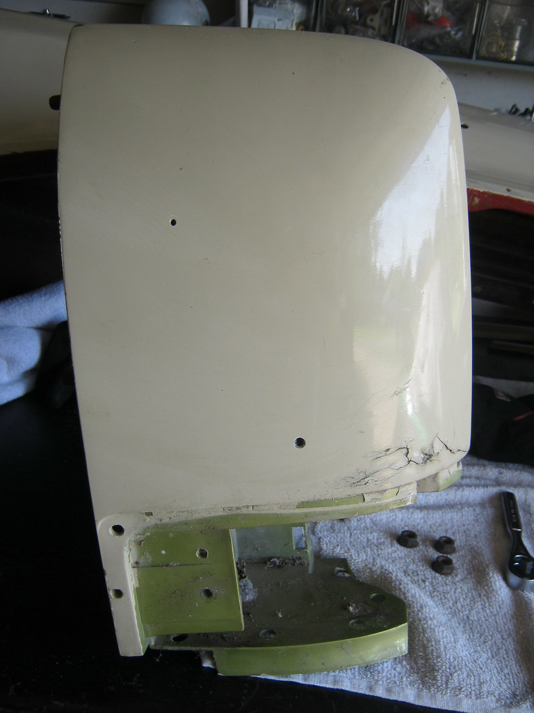
The 1/4 extension after drilling the new holes. This part is fiberglass and has had some damage. It has been repaired in the past but it will soon get a proper repair.
Now it was time to weld the unneeded holes closed. Fortunately, there were only two thanks to the SAFARI emblem alignment situation. I laid the fender on it's face, on top of a piece of aluminum, and filled the holes from the back.
I forgot to clean the front side of the fender before I welded the holes closed. I'm not sure what kind of cancerous effects the terrible smell of the melting paint has, but it can't be good.
I ground down each hole a little at a time making sure to use compressed air to cool the area to prevent warping. After getting each area smooth I repeated the process, filling in any small pinholes or imperfections that could trap air or moisture and cause paint issues later on.
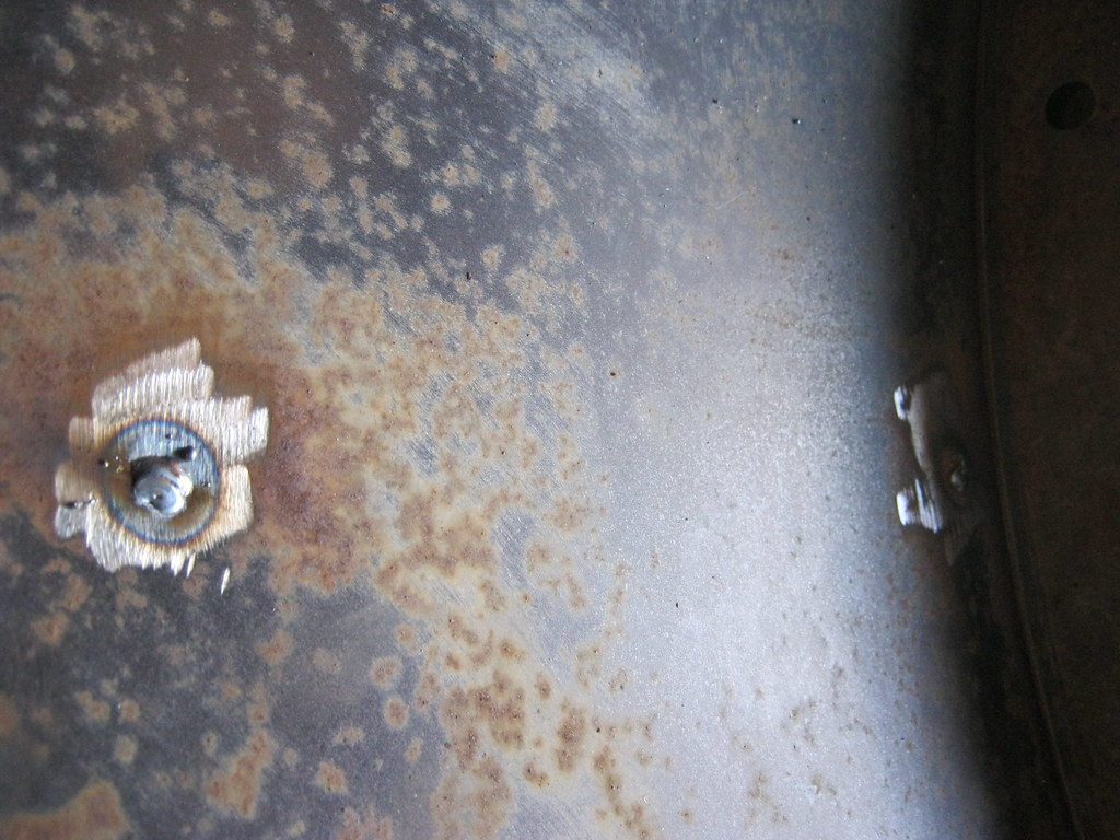
After about three passes of welding and grinding they were finally completely flush.
They turned out pretty well, with the front being better than the rear. I dug out a bit too much while grinding on the rear and there is an ever so slight divot. It's barely noticeable when you run your hand over it. This will be fixed at the body shop.
I also ground down the rear and smoothed the backside of the fender to prevent the potential of trapped moisture or air under the primer.