Friday, August 24, 2018

A Picture Is Worth 1000 Hours Researching On The Internet

I have spent a tremendous amount of the little time I have researching things online, but I don't have a lot of pictures to show for it.  The investment of new neuron connections seem to be something that is only evident in future payoffs.  I've just been having to spend 10 minutes here or 5 minutes there during the week and then stay up late and try to read as much as I can from the internet about what steps to take next.  These 18 and 19 hour days are getting tiresome but the end is in sight.

I found out my PCM does not have the correct hardware which would allow my air conditioner setup to be operated by the PCM in the way that I would like it to, so I'm going to have to get a different one.  This project is so far over budget at this point it feels like telling the surgeon amputating a gangrenous toe to go ahead and take the pelvis.

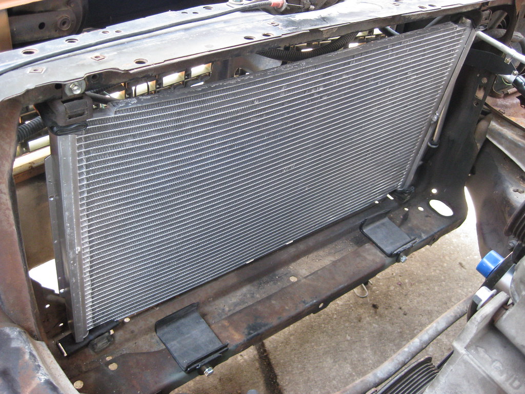
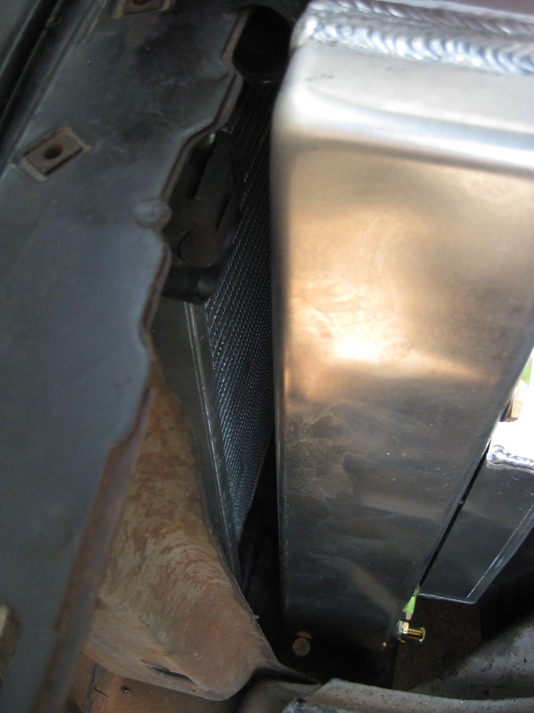
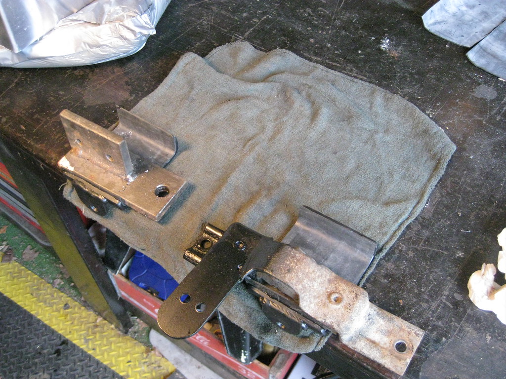
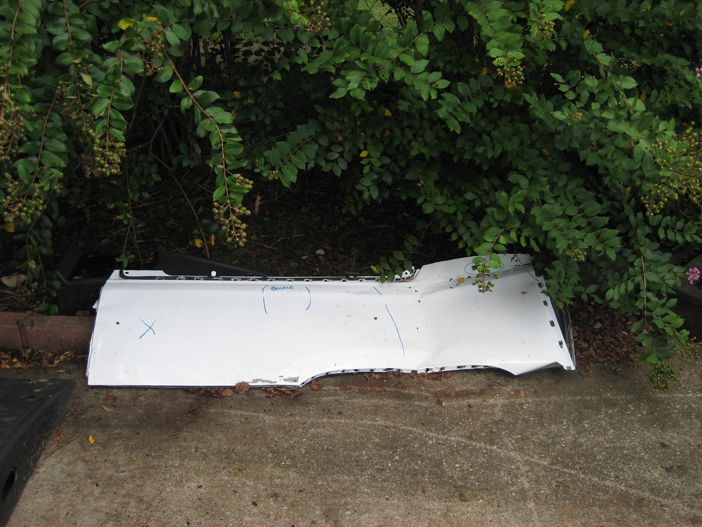
I haven't been able to find any steel the size I need to make the upper radiator mount.  I have been scrounging through the scrap piles of local body shops and the scrapyard trying to find something I could use.  Most of the metal on cars today is so thin it's barely able to be used as panels on cars, least of all structural support.  If I had a bead-roller it would open up a lot of doors to make thinner metal sturdier.  I did end up getting the quarter panel below from a Tahoe or Suburban.  I'll use this, somehow, to make the air dams that will keep the air from bypassing the condenser and radiator.  I haven't figured that part out yet, but I know it has to be done, so I'll have to make it works somehow.

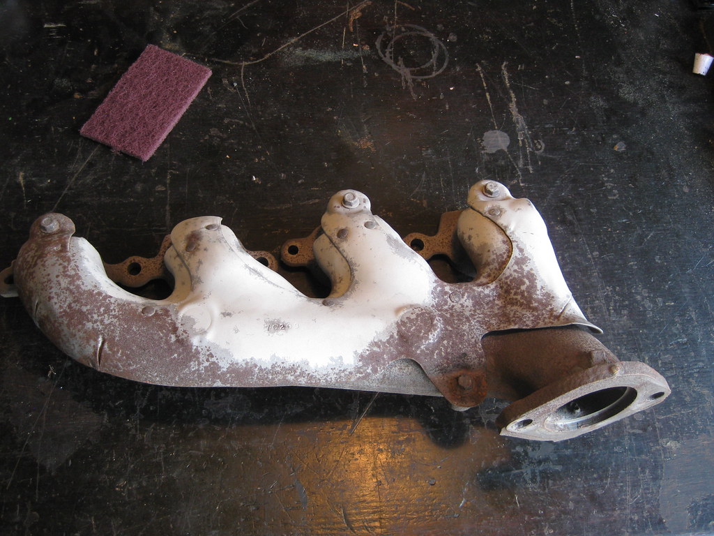
I finally got tired of people flaking out about manifolds and just bought a set of 5th generation Camaro manifolds, hoping they would fit.  The set I bought looked pretty rough in the pictures, but the person I bought them from was nice enough to sand blast them before shipping them.  I sanded them down further and prepped them for paint.

Header paint is expensive.  That's all I've got to say about that.  I had originally planned to paint the heat shields silver to more closely match what they originally looked like, but I already had this cast grey in the heat resistant paint so I used it.  I was surprised to find that I actually like this color combination better.  It's a bit more low key and blends in better with the crusty looking engine and engine bay.  I was not about to try to remove the head shields and deal with all the broken bolts so I had to tape everything off, which took a long time.  It kept springing up summer showers while I was trying to paint, so that also delayed things.

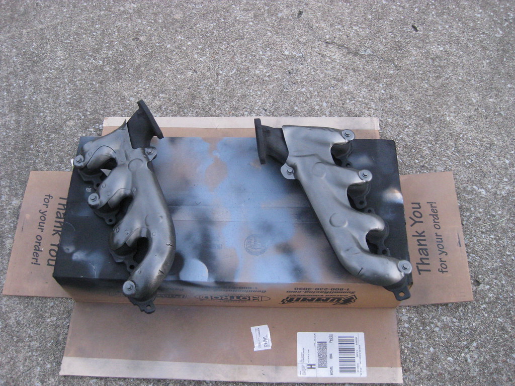
I painted the manifolds black because I figured they would blend in better as they aged.  I ended up putting on two coats of "very high heat" resistant primer, two coats of basecoat and two coats of clear coat.  I'm not sure, but I hope that will prolong the typical manifold paint flaking that always takes place.  Or maybe the paint will be too thick and it'll all fall off.  Only time will tell.  I coated the inside of the tubes as well at the advice of someone I met in the store buying the paint.  Maybe it will help cut down on the heat and paint flaking, or maybe not.  Again, I didn't figure it would hurt anything and time will tell.

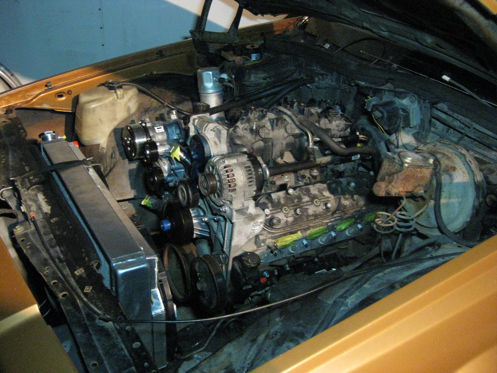
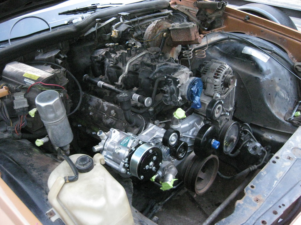
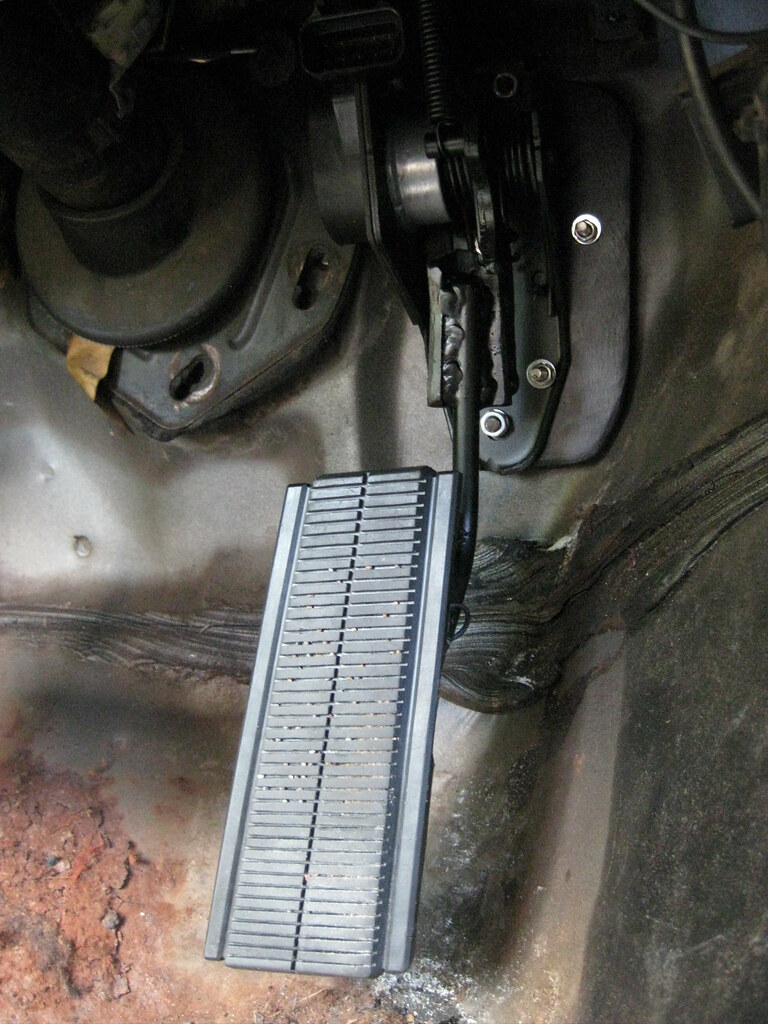
I got a lot of small things mounted like the evap solenoid block off plate, the coils, new spark plugs and coil wires, the exhaust manifolds, the starter, etc.  One of my new plug wires was bad so I've had to order a single one from the dealer.  They must be made out of gold. $$$.

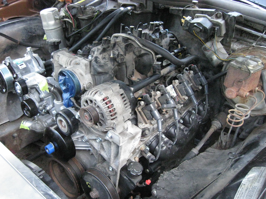
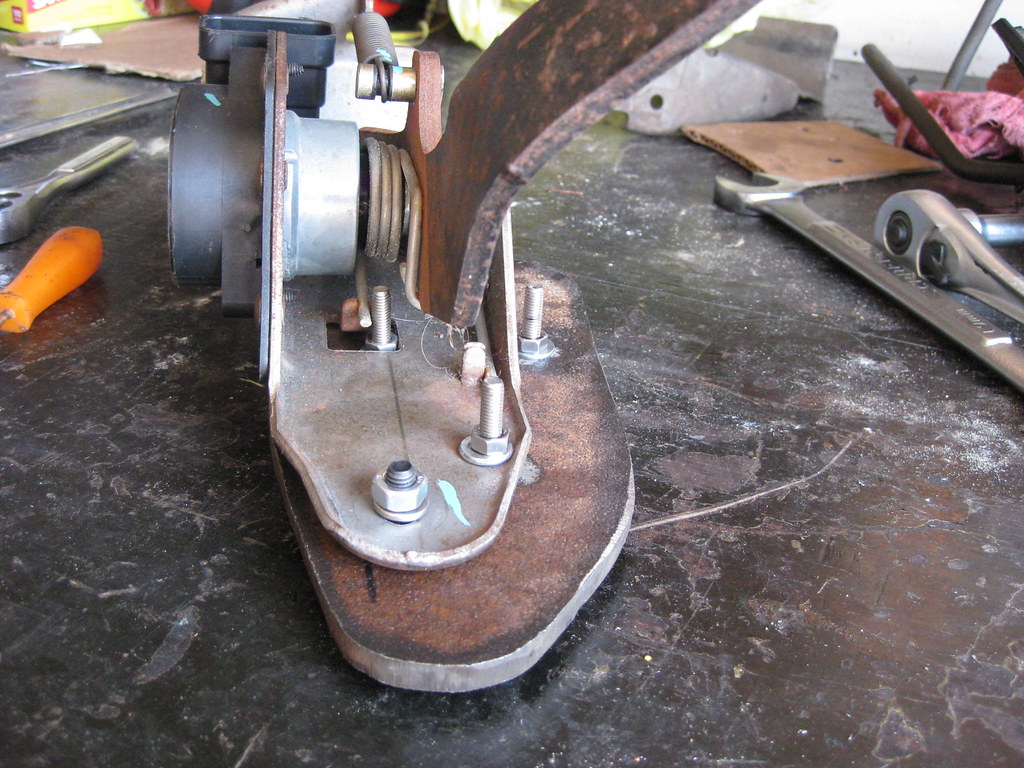
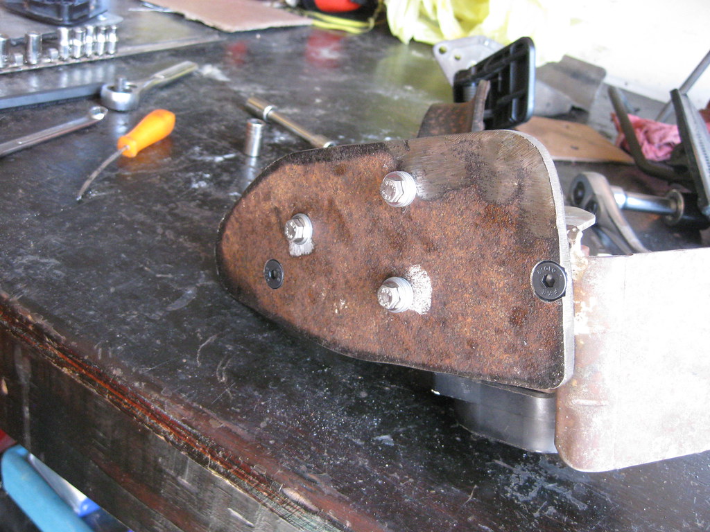
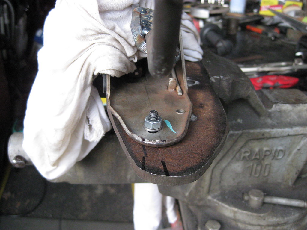
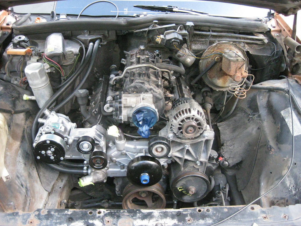
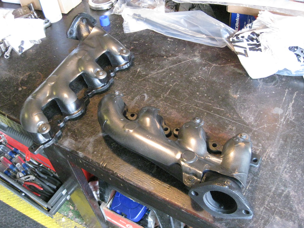
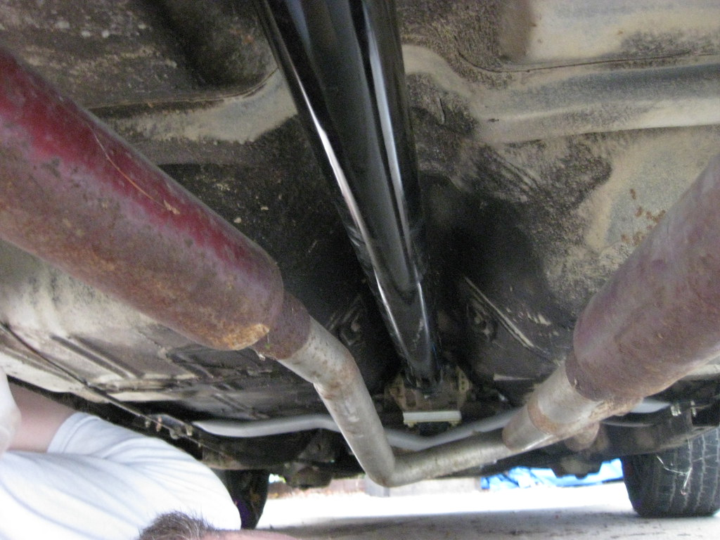
The exhaust manifold on the driver side fits great.

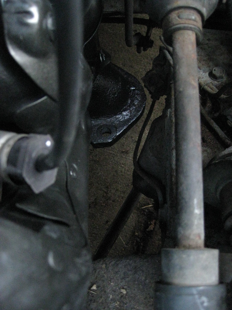
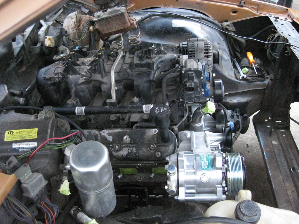
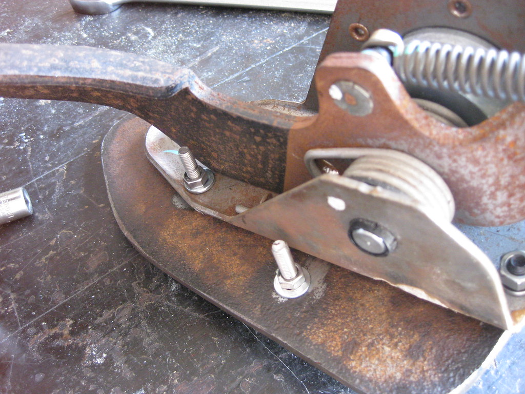
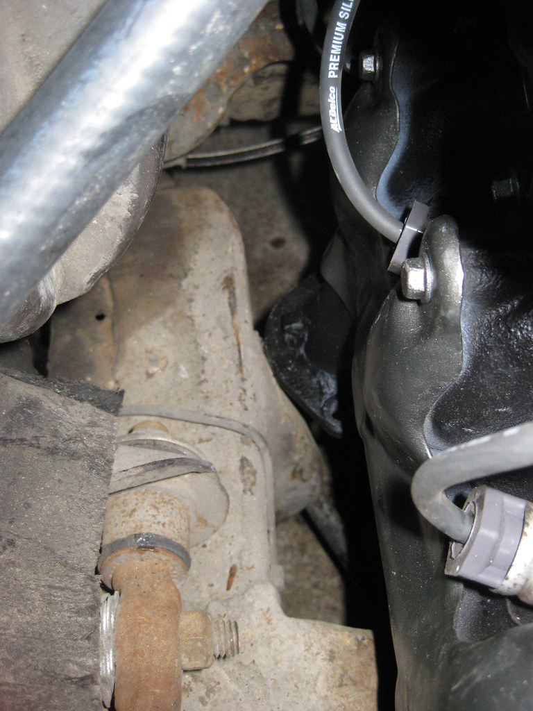
The passenger side is either touching the frame, or it's so close it would have to be measured in microns.  I'm not sure how much of this flange I can grind off without effecting the way the exhaust will mount together, so I'm going to let the exhaust shop handle this to their liking.

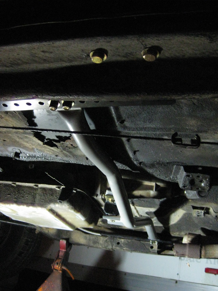
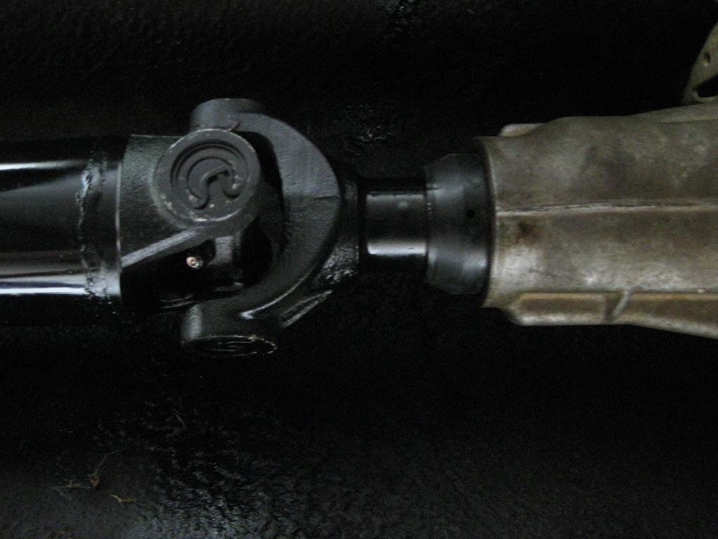
One great thing about having a father that's retired is he can run and get parts during normal business hours.  Dad dropped off my transmission yoke at the driveshaft shop and then picked it up when they had made a new driveshaft to my specifications.   

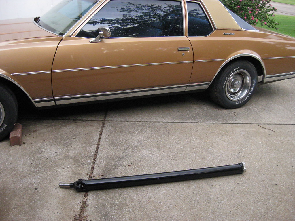
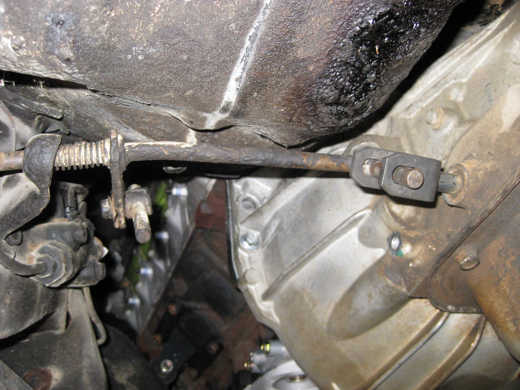
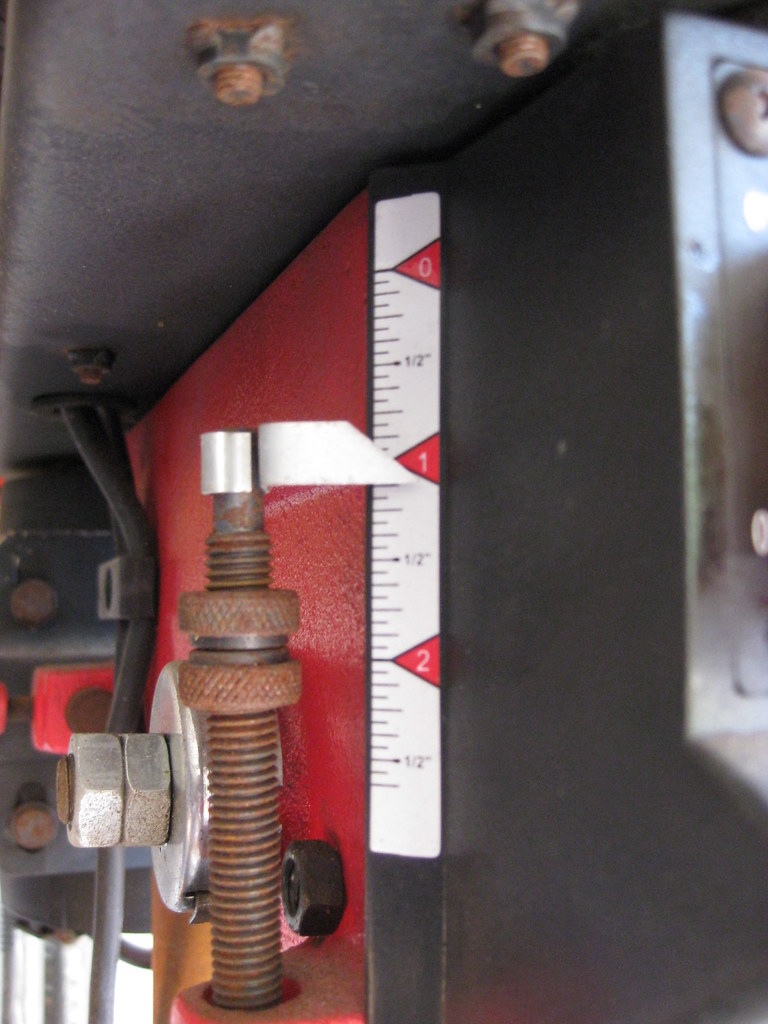
I think I jacked the car up and took this measurement around 5 times, on 5 different days.  Each time I would think I had the measurement taken in the correct way and then I would learn something new that made me realize I needed to remeasure or double check what I had done.  I installed the driveshaft holding my breath and it fit exactly right.  Relief.

The yoke had just the right about of run out.  Now I just hope the BRP transmission mount got the driveline angle correct, as it was advertised to do.  My experience with the rest of their products on this car has left me less than confident.

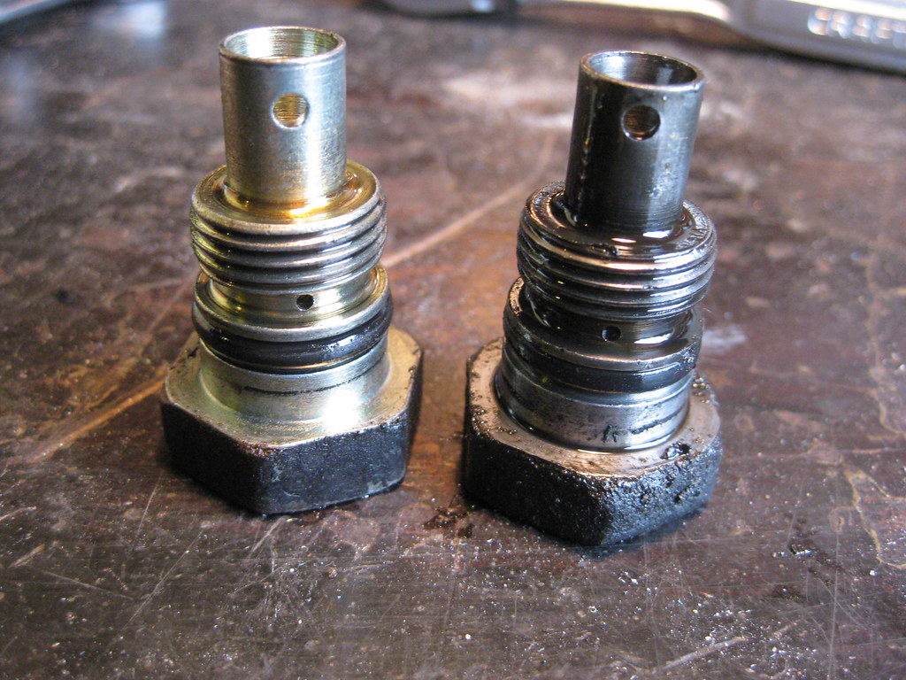
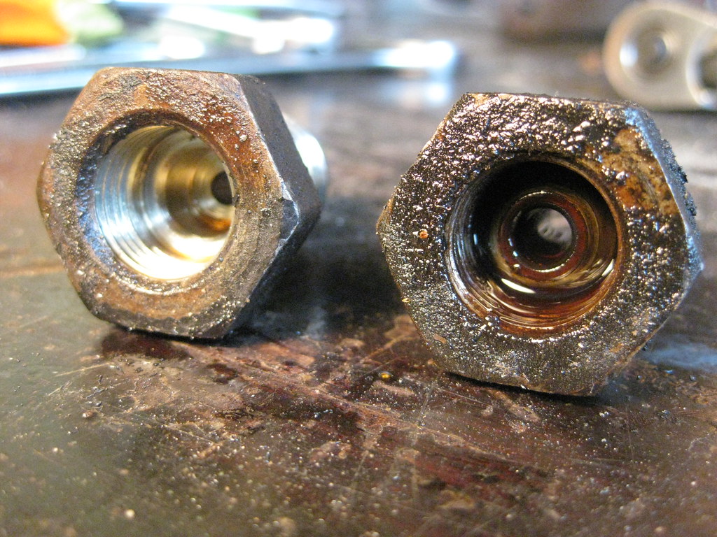
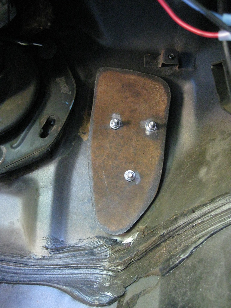
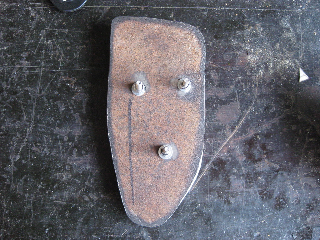
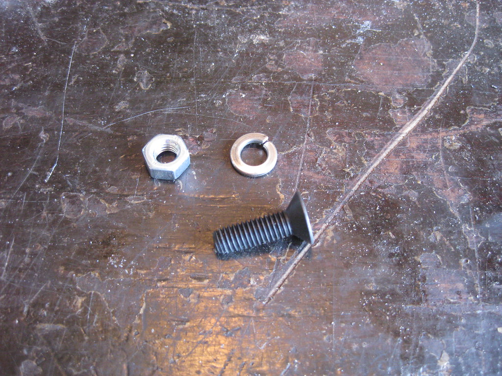
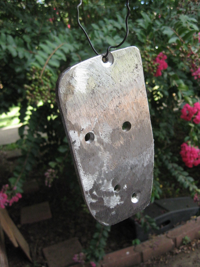
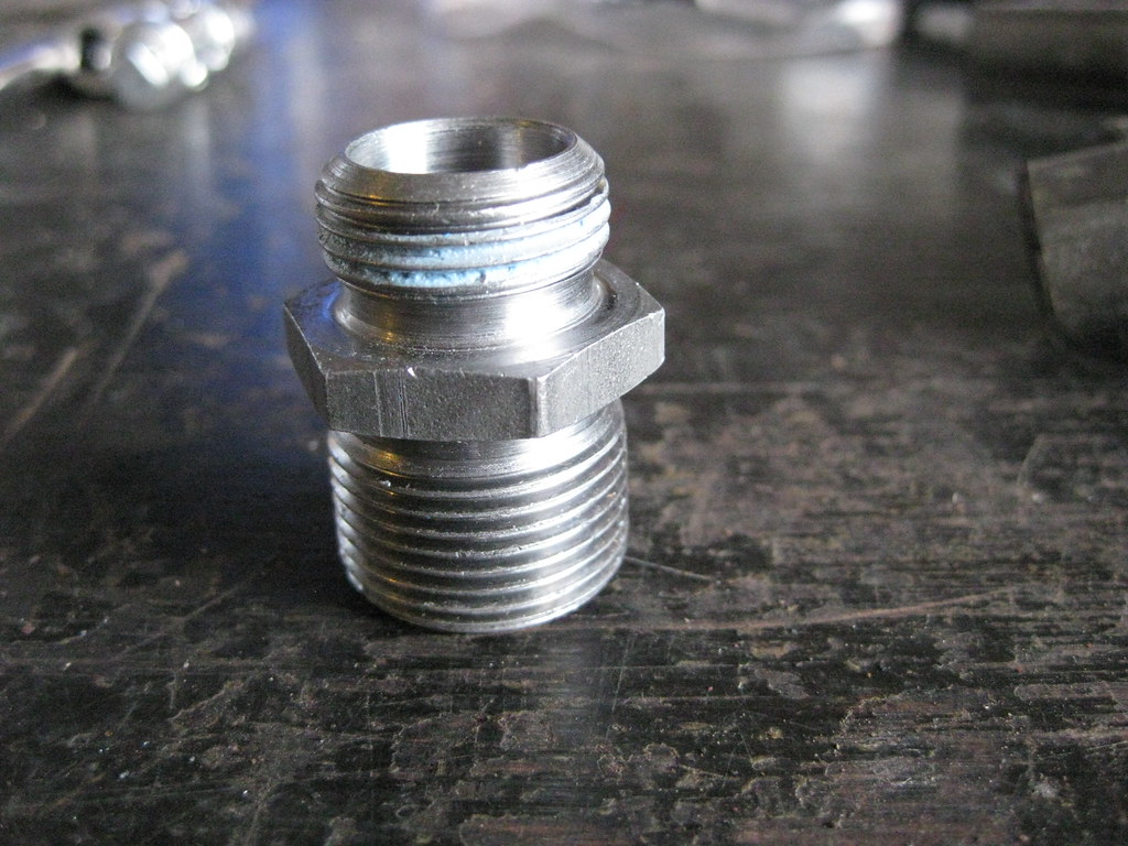
I bought an oil filter for a 2004 Avalanche, because that's what kind of engine I have in the car.  I got home, filled it full of oil and realized, I have a 2004 Avalanche engine in my car, but the oil pan for that engine is now sitting in a barn.  I have a Holley oil pan on the engine.  So I gave the oil filter to dad for his next oil change on his Suburban and bought the correct oil filter, a PF48.  When I went to install the oil filter it suddenly occurred to me that there's nothing to screw it to.  Go back in time to earlier in this story and I purchased the Holley oil pan, which comes with two provisions for turbos, if one were so included to add them.  I'm not using turbos so I plugged the holes with the provided plugs.  I had assumed at that time, without thinking, that the piece pictured below was an adapter for a turbo.  Fast forward to me looking at the oil pan like a calf at a dried up sow and I immediately realized that piece was the oil filter adapter, but where had I put it?  At this point my entire garage looks like that jar of loose screws and nuts that old men always have in their shop and I had no idea where I had put this thing.  Was it in one of the boxes I'd stored in the barns far away? Was it in dad's barn?  Was it in some random box in my garage?  I had no idea.  I ruminated on this for quite a while and finally gave up and as so often happens when you have succumb to defeat, suddenly it occurred to me that I thought I had wrapped this piece up and put it in a storage pin sitting over my workbench.  When I looked, it was right where I thought it might be.  What a relief.  40 foot pounds later (and 1/4 turn past hand tight on the filter), I had an oil filter on the car.

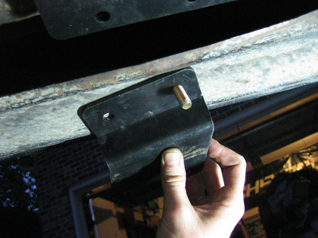
My childrens' babysitter called in late last night with a stomach bug so I had to take off work and keep them.  I used this time to take a field trip to the steel supply store in Nashville and picked up two pieces of 1/8" steel, which they cut to my specifications.  Unfortunately, they didn't have a metal brake.  I'll use one of these two pieces for the upper radiator mount.  I'm still not sure how I'm going to get the piece bent into shape, but at least I have the steel now.  The other piece will be a mount for the PCM and new fusebox.

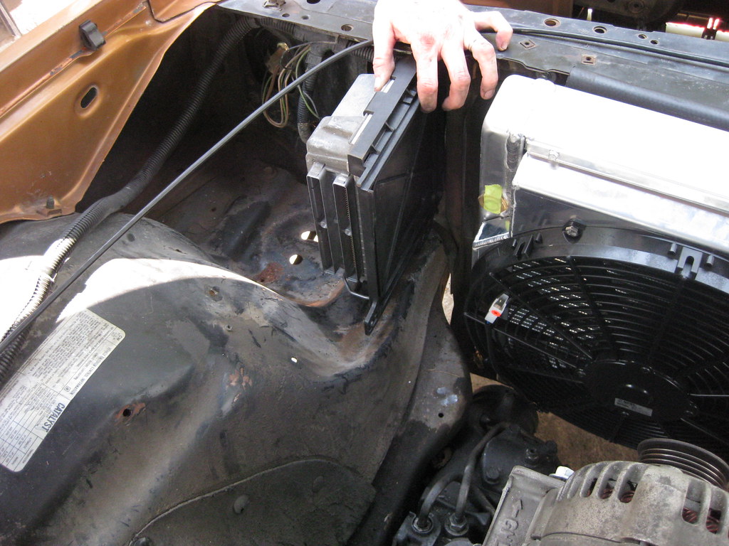
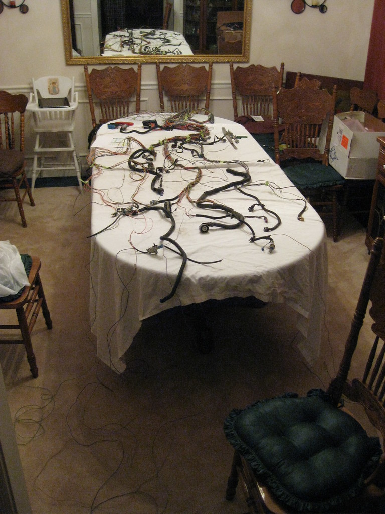
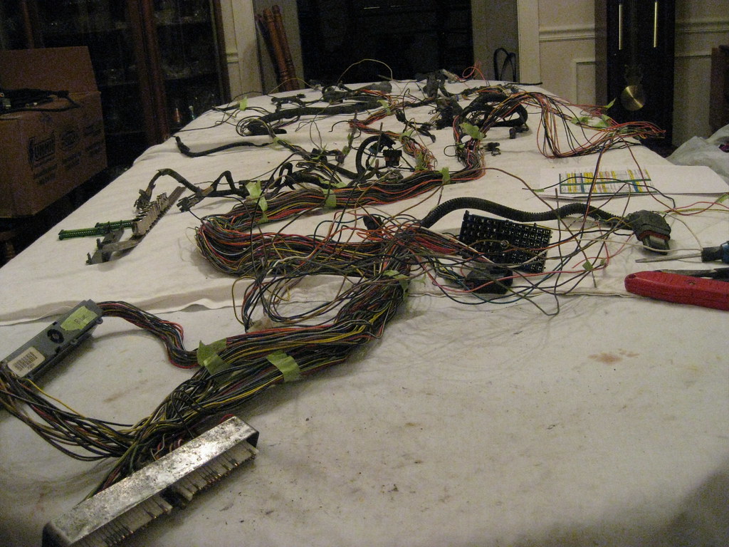
I spent a ridiculous amount of time reading about what kind of fusebox I would want to order for my needs for this car.  There is so much information it is entirely overwhelming.  Fortunately I found a superb write up online about this very topic.  I printed out every page of the write up and put it in a 3-ring binder and have been using it like an encyclopedia for a pre-internet research final due at 8:00 am tomorrow.  I was up past midnight one night trying to figure out all the correct connectors and pieces I would need to order and how they would fit together.  After looking at my options I have decided on a way to mount the PCM that I believe will not only be the cleanest appearing installation, but may also still allow me to run the air filter over to the driver side of the engine. 


American Mounty

Not a lot to show for a whole days work.  I did take part of the day to gather and store all the extra parts in the barn loft, which will allow me to get the trailer out of the driveway, which will allow me to move the car closer to the garage, which will mean a little bit more shade during the day.

Upon some advice I ended up ordering a condenser for a 1996 Caprice.  It was a much better option than the universal condenser I was previously considering.  This condenser already has the hardlines run in the correct location.  This unit was a bit shorter in height than the previous unit.  I was able to reuse the original rubber mounting cushions.  I had to relocate the upper driver side mount toward the fender.  Because this area is boxed I had to drill a hole and use a self tapping screw.  It took quite a long time getting the exact combination of location and extra rubber correct.  In the end it mounted tight and secure.


After a lot of trial and error I ended up marking and putting the lower radiator mounts on the radiator and then installing them together.  As you can see below the condenser lines fit just right.  I still haven't figured out a good solution for the upper mount.  I can't find a piece of steel the right size to make something and I cannot find a metal break.  I also cut a piece of heater core hose as a cushion between the core support and the radiator, just in case.

The PCM mount came in while I was working.  I was hoping to mount the PCM tucked away and hidden in this location, but after test fitting it I realized that this option isn't going to work.  It would also cause an extensive amount of modification to the wiring harness.

This leaves me with a lot of less desirable options for locations of the PCM.  This seems to be the best option so far for several reasons, but I'm not sure how I feel about it being this close to the radiator.

The radiator and condenser have a gap of a little over an inch, which is more than ideal, but it is as close as I can get them and seems to be close to the original distance.  I will need to add some air dams to keep the air going through the condenser.

I took the gear selector fork off of the old 350 turbo transmission and it fit on the 4L60E.  At first it seemed certain it wasn't going to fit but after a lot of coaxing it finally came together.  I'll have to remove it one more time to install the neutral safety switch when it comes in.

I finally got the BRP transmission crossmember fully mounted.  I continually regret purchasing this kit.  The crossmember kit is essentially a universal kit.  The bolts in the center transmission mount were too short.  When I contacted the company they told me to just go buy longer bolts.  The transmission crossmember requires an extra bracket on the driver side.  The instructions with the kit, which must be downloaded in a PDF from the internet, do not include this extra bracket and show pictures of a different crossmember that is longer and do not require the extra piece.  When I looked up instructions for different types of cars it does include this extra bracket.  Also, the bracket does not fit the car as instructed.  Given all of this I began to suspect I was sent the wrong kit.  I contact the company again and they informed me that this correct and to ignore the crossmember in the directions.  Also, the bracket shown requires holes to be drilled in the frame, but it mounts on top of the frame.  This means there's no way to located or mark where the holes should be.  I ended up having to hold my finger in the hole on top of the frame where the bracket will mount and try to match that location with my other finger on the bottom of the frame.  I've had three people look at the instructions and try to understand how this piece should be installed and none of them can figure it out.  I eventually just took the piece, ignored the instructions, and found a way to make it fit.

I then disassembled the extra bracket and used it to help locate the second bracket hole by holding it under the frame.  I basically used a punch to draw an arc indicating the possible locations for the second hole and then reinstalled everything correctly, held my finger over the hole and guessed the best location.  Again, the reason I ordered this kit is that is appeared, because of the description and instructions which I viewed ahead of time, that it would require no drilling or modification.

At long last, everything was bolted up and tightened down.

There are quite a few pieces on order that I'm waiting to come in.  This thing is starting to look like a driveable car.

Sunday, August 5, 2018

The Jig is Up


Here are the pictures of the Holley A/C bracket with Sanden 508 fully installed, minus the belt.


I wasn't exactly sure what to do about plumbing the power steering and then someone on the forums mentioned that the original lines should fit.  I pulled the original lines off of the old engine and they not only threaded into the hole but they also lined up perfectly.  Apparently the new pump is almost exactly in the same location as the old pump.

There is a 3rd line on the 2004 power steering pump that was originally used as a return line for the hydraboost brake system on the donor Avalanche.  I'll crimp this line off and seal it.

I later found out that even though the old Caprice power steering line threaded into the back of the 2004 power steering pump, the new and old lines have different styles of fitting and they have different fittings internally in the back of the pump and that would not allow for a good seal.  There were several options here and companies make adapters to fit the old hose to the new hose, but since I have the old pump I was able to swap the fittings in the back of the pumps that the power steering lines threads into.  I pulled the fitting out of the old motor.

They look identical from the outside.  The 2004 fitting is on the left and the original fitting is on the right.

however inside is a different story.  The 2004 fitting is on the left, the original fitting is on the right.

After installing the old pump fitting in the back of the new pump the lines fit perfectly and bolted up just fine.  That was a relief.

I finally prepared the dining room table for operation of the wiring harness.  Funny enough, these sheets I'm using were actually used at a funeral home for covering embalmed bodies, brown blood stains and all, so this isn't the worst operation they've seen.

Here's the harness splayed out.

I started removing the loom and black tape.

And spaghetti went everywhere.  I'm a bit overwhelmed here as I really don't fully understand what I'm doing.  I'm just trying to take it one small step at a time.

I started back to work on the new gas pedal.  I got the holes drilled in the mounting plate to attach it to the firewall.  There were many different ways to accomplish what I needed to do.  While I was at work I would design this in my head and then piece together the parts a little at a time.

I marked a plumb line on the plate while it was mounted in the car so I could align the pedal assembly straight.

One thing that made the mounting difficult was avoiding interference with all of the bolts coming through the plate while still getting the new pedal positioned properly.

I had to drill a hole in the pedal assembly with the hand drill because it wouldn't fit in the drill press.

This shows how the bolts were positioned so the pedal could mount flat without interference.  My original plan was to use spacers between the pedal and the plate but I found this didn't give the the stability I wanted.

I also didn't want anything sticking out of the back of the plate between it and the firewall.  The new pedal had two mounting holes, one on the bottom and one on the top, shown here.


I decided to countersink the bolts so they would sit flush with the back of the plate.

I was able to use the drill press to drill the right depth without going too far.  The 1/4 inch steel gave me enough material to achieve this.


Everything mounted up as planned.

And there was no interference with the pedal travel.

The silver bolts will be on the outside of the firewall when the assembly is mounted.

Then it was time to relocate the pedal.  I made this jig to help me put the new pedal in the right place.

I mounted the original assembly to the jig and marked where the pedal sat.

I used a drywall screw through the cardboard to locate the depth and height of the top of the pedal,

I mounted the assembly so that the bottom of the pedal aligned at the cardboard and I then marked that location on the cardboard.

Since the new pedal assembly will use the original holes I was able to mount the new pedal assembly to the same jig and reference the marked position of the old pedal.  I drew a line on the new pedal arm for the cut.

And I chopped it off with my dwindling supply of cutting wheels.

I wanted to keep the original pedal.  The new pedal arm would not mount to the original pedal so I had to cut the original pedal arm and mate it to the new pedal arm.  With the new pedal assembly mounted on the jig I was able to locate where the pedal should be and begin to work from there.

For the entire build of the car so far, this was by far the most frustrating process yet.  What seems like a quick and easy process in pictures actually equates to several hours of test fits and failed ideas and bruised fingers pushing the now stubby pedal arm down with no leverage.  I did take the spring off.  The electronics required a special socket to remove, so I was not able to take this apart.  Because of the shape of the original pedal and the way it swiveled on the arm there were certain angles which could not be modified.  Because of this, no matter in what position I put the pedal it would make contact when the arm would be mashed down fully.  As I stated, I literally worked on this for hours trying to get the pedal to reside in it's original location without making contact when the pedal would be pushed to the floor.

I wanted to keep the welding on the new pedal arm to a minimal to keep the heat away from the electronics.  Because of this, I didn't want to cut the arm too short and then have to reweld material back on if it wasn't absolutely necessary.  As a result I went through several iterations of cuts to the original pedal arm, each time cutting a little bit more at a slightly different angle until I finally found one that was as close as could be achieved.  I finally reached a point where I knew this was as good as it was going to get and I would have to make this it and deal with whatever else later.  I welded a plate to the original arm with wet rags and vise grips used as heat sinks attached to the arm to protect the electronics on the assembly.

I then used the pedal and arm to locate where the new arm should be welded.  It wasn't very pretty, but it's on there.  Again, I wanted to keep the welding and grinding down to a bare minimum.

The position isn't exact but after a lot of playing with options I was able to get it relatively close.

The pedal arm did end up with some interference, but it wasn't too bad compared to the previous versions.

I marked the areas and ended up cutting off the bottom of the mounting plate and using a round file to cut a relief in the bottom of the pedal assembly and taking some length off the bolt.

At long last the piece was ready for primer and paint.  This simple piece of steel took many hours just to get to this point.

The finished assembly, after paint, bolted together.


Start to finish, I probably have 16-20 hours in this assembly.  Even though it looks pretty straight forward the placement of all of the pieces was so critical that finding a way to make all the parts work together in the right location was very time consuming to figure out.  I understand it would have been much simpler to drill new holes in the firewall and put the pedal where it needed to be, but that's not how I wanted the finished product to be and one great thing about a project like this is you can do it however you want.

Here's the end result.

It seems to work well and allows full travel of the pedal with no interference, and I get to keep my original pedal.

The new radiator came in and fortunately even though it has a transmission cooler built in it is the same exterior depth as the radiator I returned so I was able to reuse the mounts I had previously made without modification.  I glued some rubber inside the mounts and put some weight on them until it dried.

I flushed the heater core using this attachment for a garden hose I made a few years ago.

I finished up by running the heater hoses.