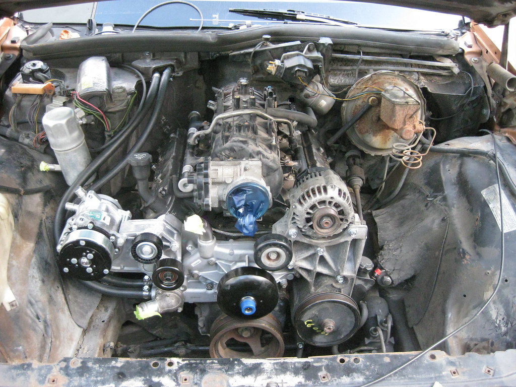
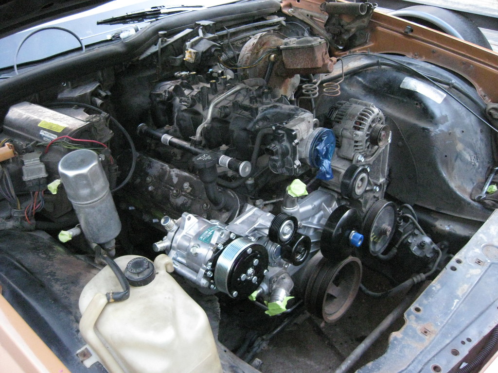
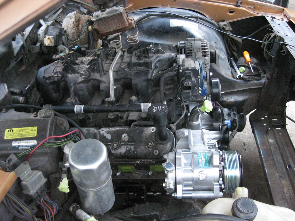
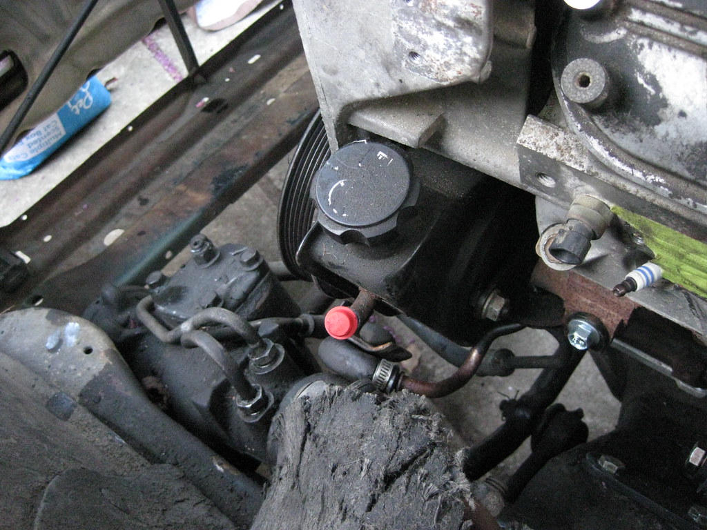
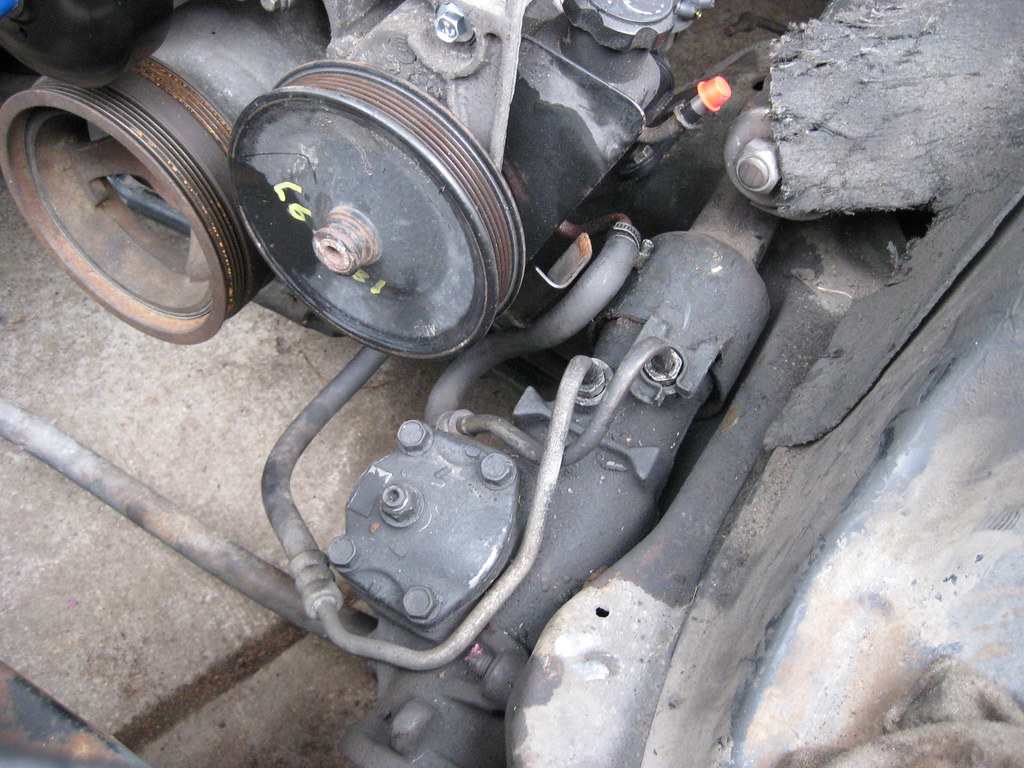
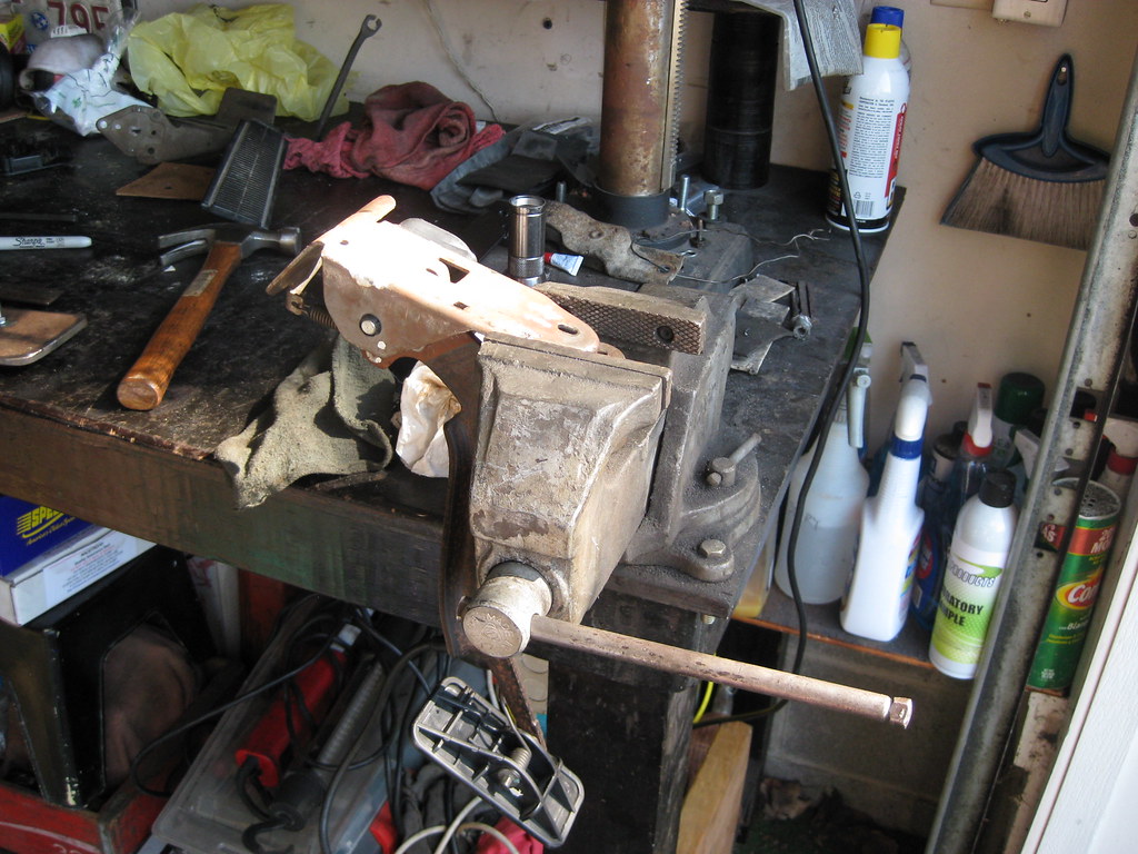
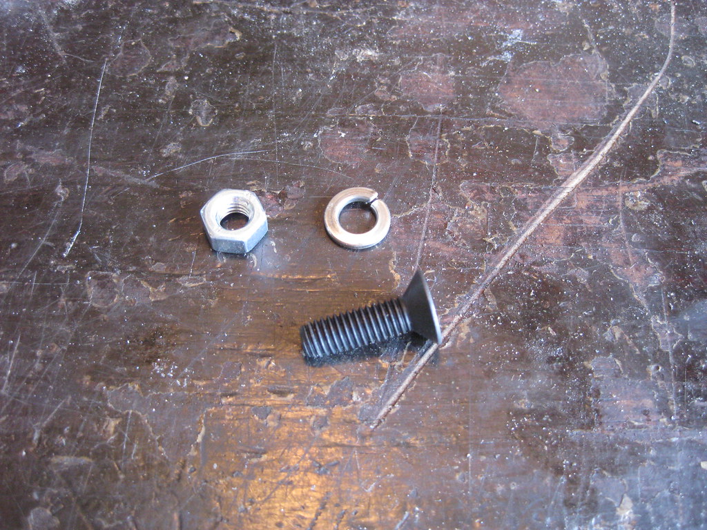
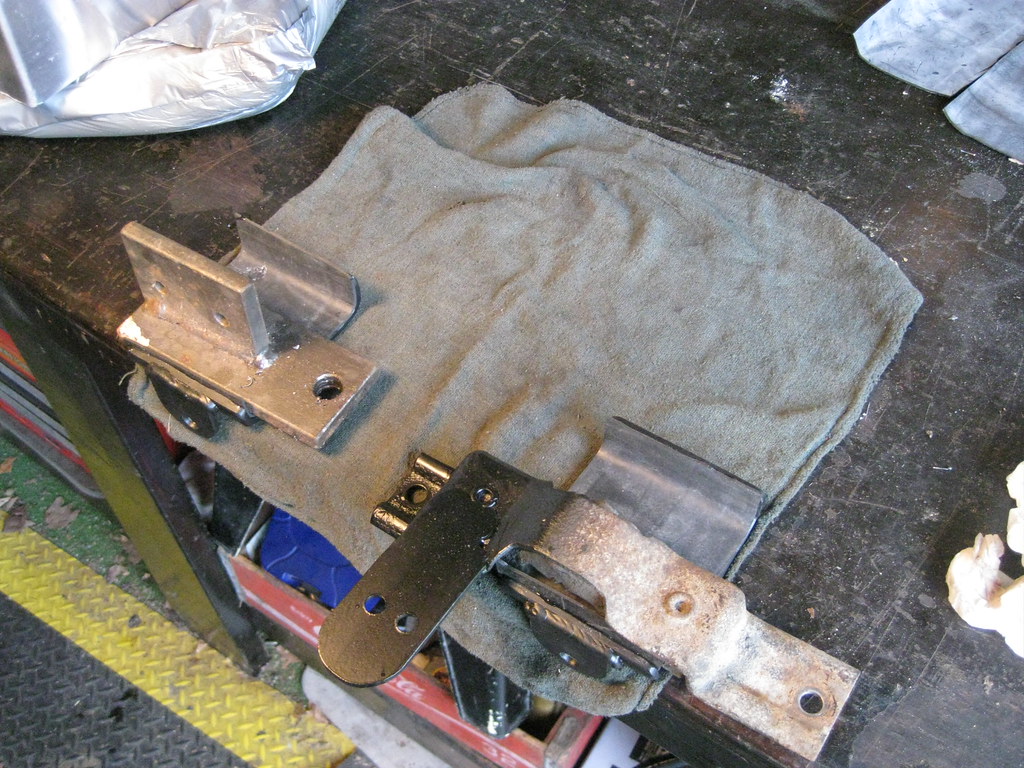
Here are the pictures of the Holley A/C bracket with Sanden 508 fully installed, minus the belt.
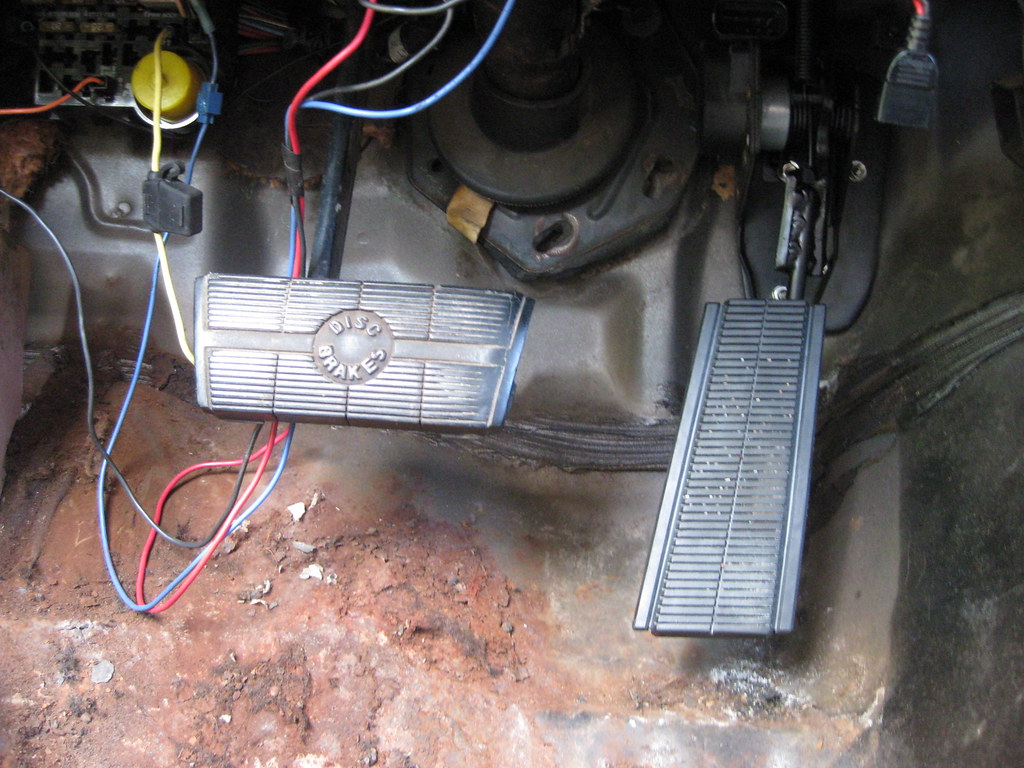
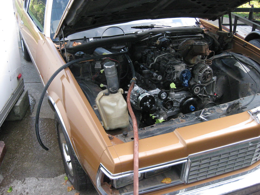
I wasn't exactly sure what to do about plumbing the power steering and then someone on the forums mentioned that the original lines should fit. I pulled the original lines off of the old engine and they not only threaded into the hole but they also lined up perfectly. Apparently the new pump is almost exactly in the same location as the old pump.
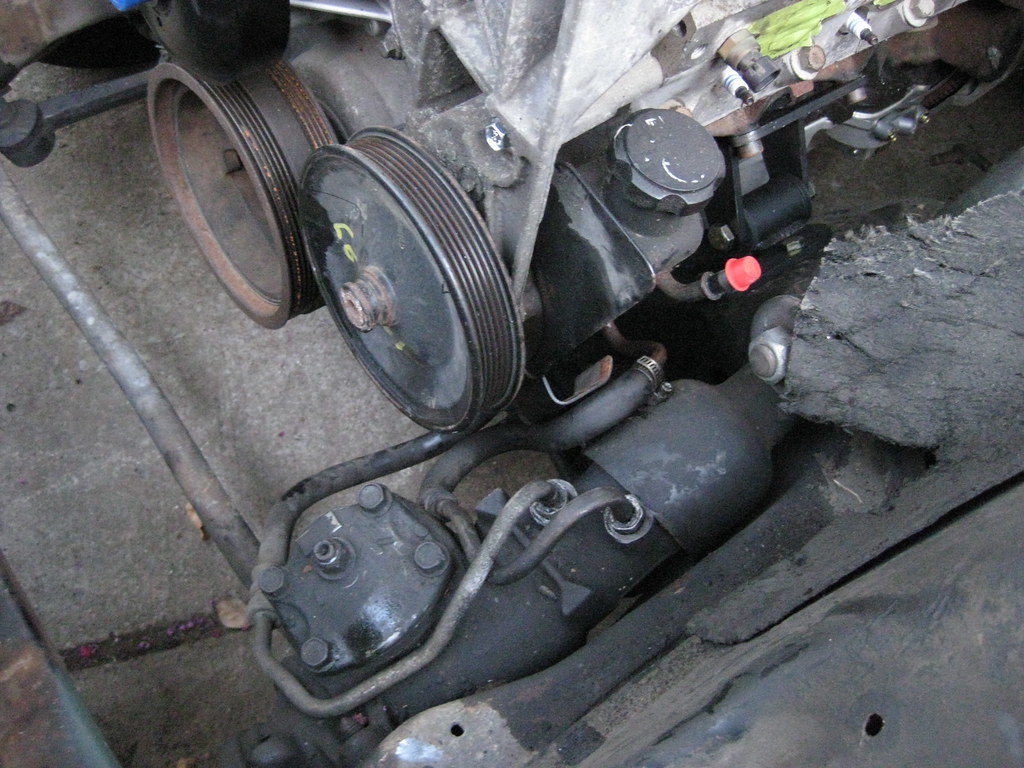
There is a 3rd line on the 2004 power steering pump that was originally used as a return line for the hydraboost brake system on the donor Avalanche. I'll crimp this line off and seal it.
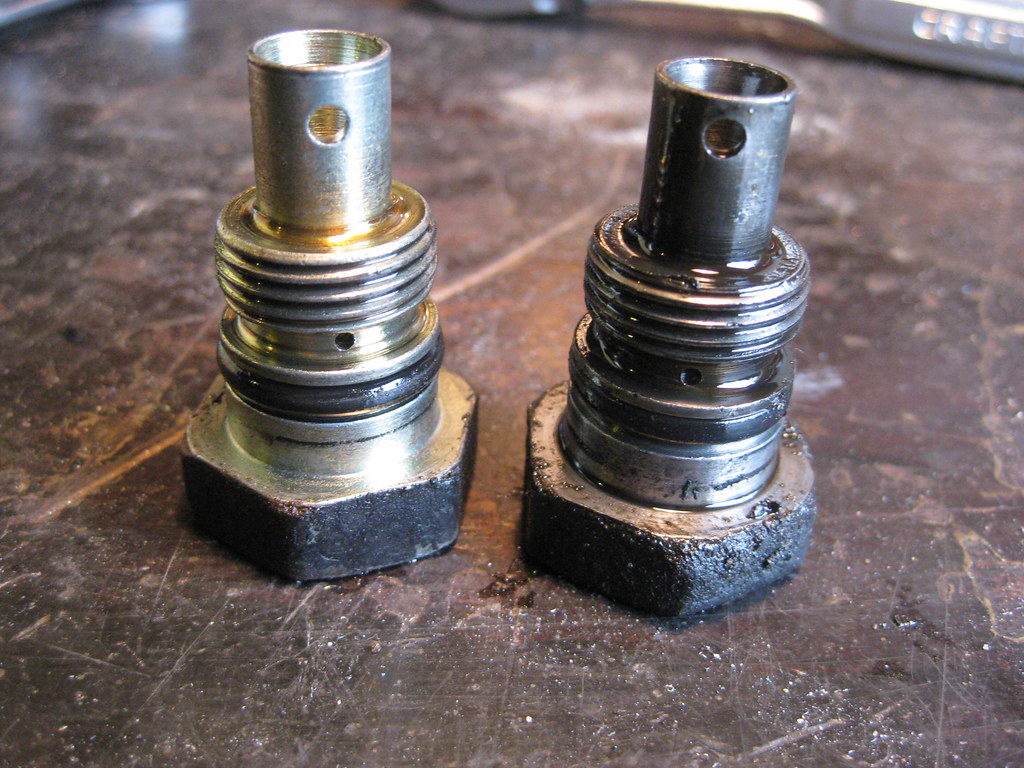
I later found out that even though the old Caprice power steering line threaded into the back of the 2004 power steering pump, the new and old lines have different styles of fitting and they have different fittings internally in the back of the pump and that would not allow for a good seal. There were several options here and companies make adapters to fit the old hose to the new hose, but since I have the old pump I was able to swap the fittings in the back of the pumps that the power steering lines threads into. I pulled the fitting out of the old motor.
They look identical from the outside. The 2004 fitting is on the left and the original fitting is on the right.
however inside is a different story. The 2004 fitting is on the left, the original fitting is on the right.
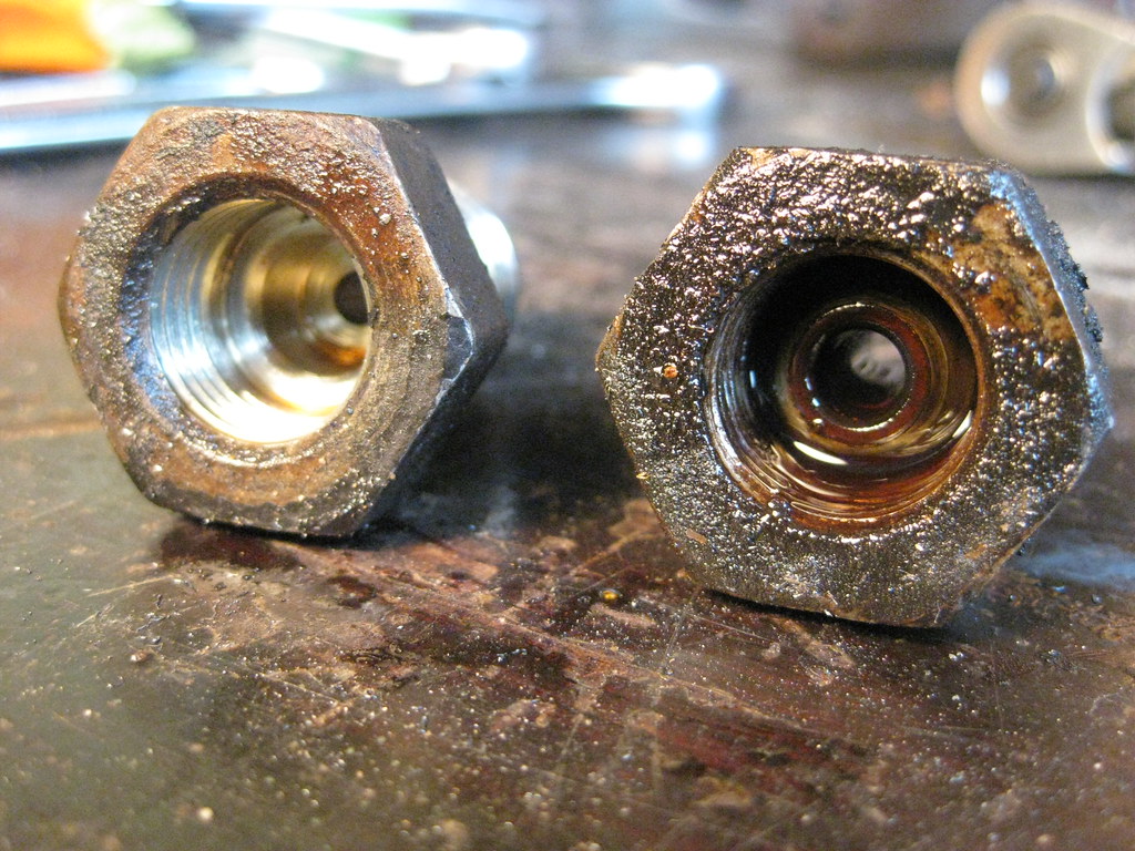
After installing the old pump fitting in the back of the new pump the lines fit perfectly and bolted up just fine. That was a relief.
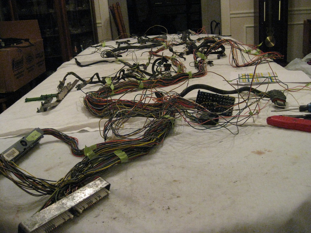
I finally prepared the dining room table for operation of the wiring harness. Funny enough, these sheets I'm using were actually used at a funeral home for covering embalmed bodies, brown blood stains and all, so this isn't the worst operation they've seen.
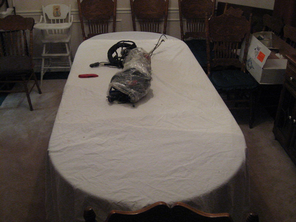
Here's the harness splayed out.
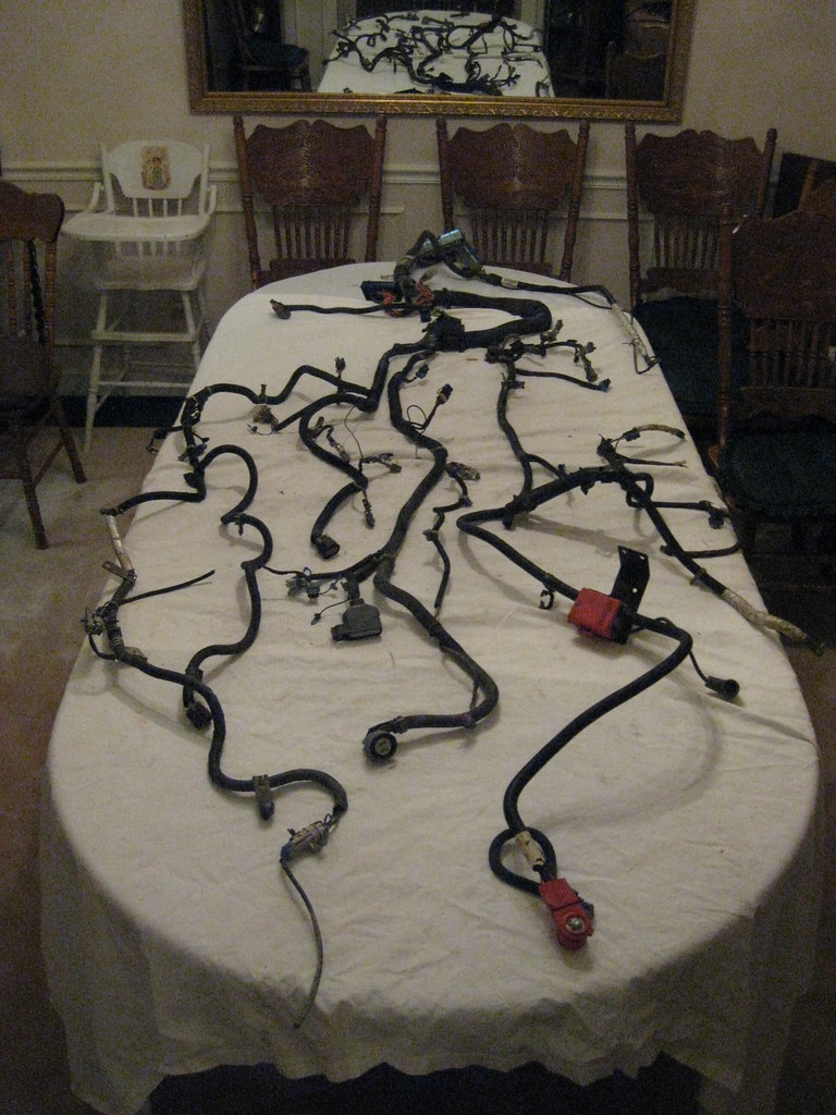
I started removing the loom and black tape.
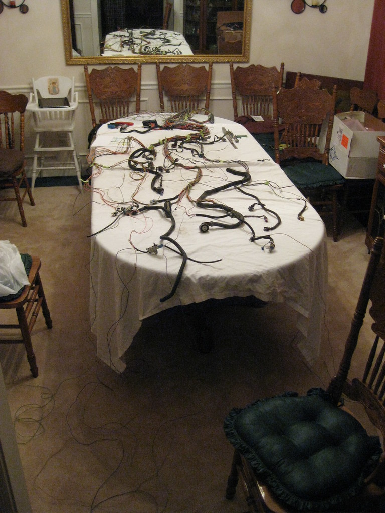
And spaghetti went everywhere. I'm a bit overwhelmed here as I really don't fully understand what I'm doing. I'm just trying to take it one small step at a time.
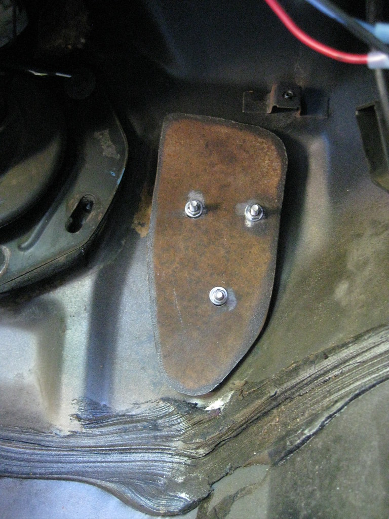
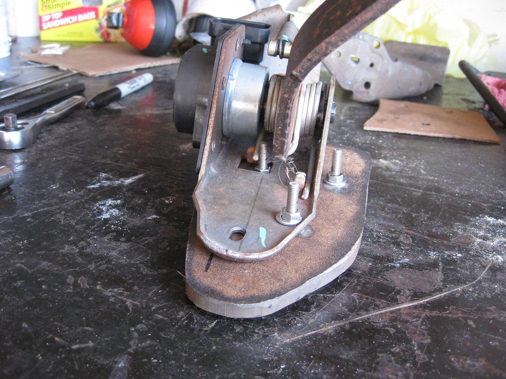
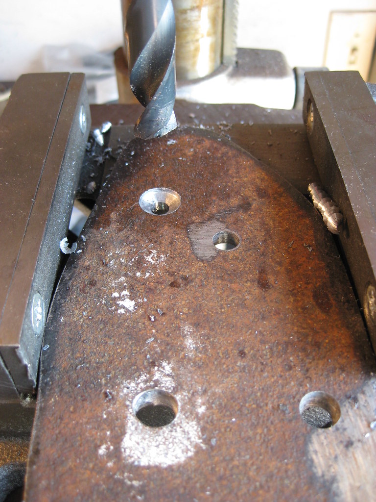
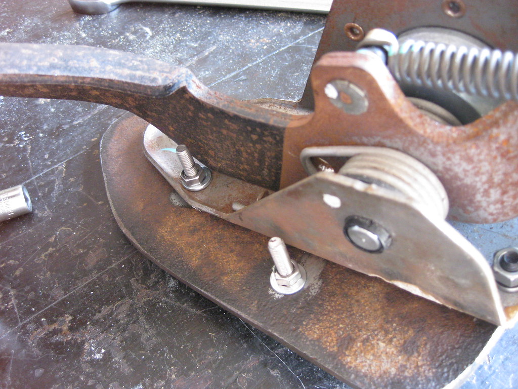
I started back to work on the new gas pedal. I got the holes drilled in the mounting plate to attach it to the firewall. There were many different ways to accomplish what I needed to do. While I was at work I would design this in my head and then piece together the parts a little at a time.
I marked a plumb line on the plate while it was mounted in the car so I could align the pedal assembly straight.
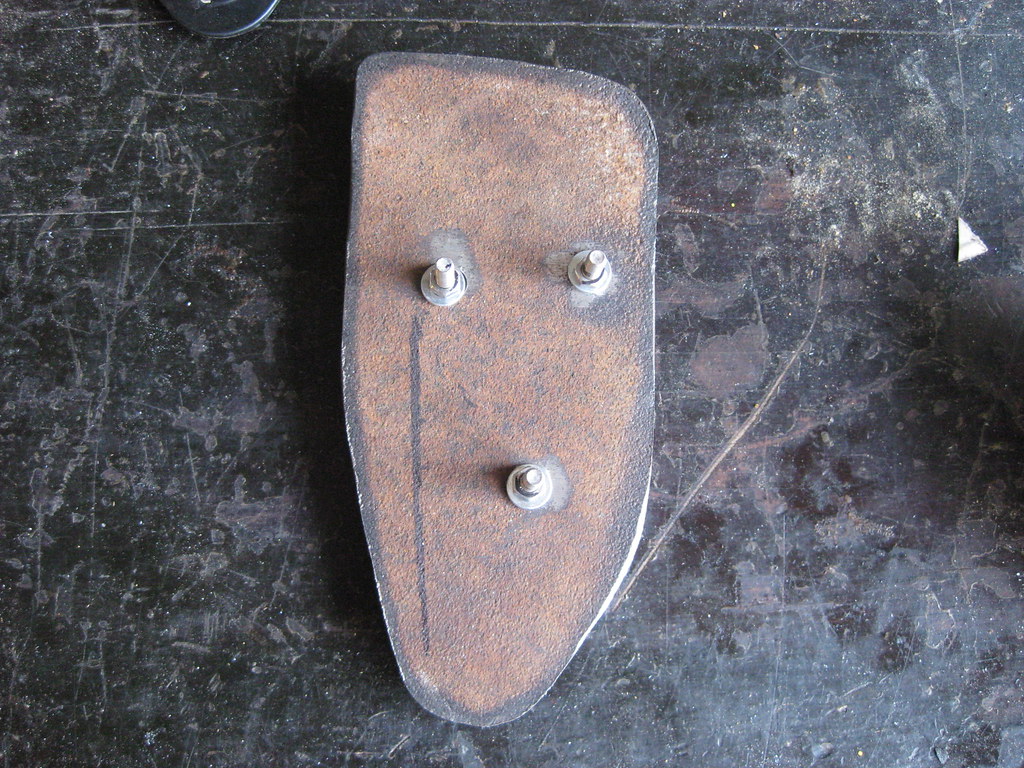
One thing that made the mounting difficult was avoiding interference with all of the bolts coming through the plate while still getting the new pedal positioned properly.
I had to drill a hole in the pedal assembly with the hand drill because it wouldn't fit in the drill press.
This shows how the bolts were positioned so the pedal could mount flat without interference. My original plan was to use spacers between the pedal and the plate but I found this didn't give the the stability I wanted.
I also didn't want anything sticking out of the back of the plate between it and the firewall. The new pedal had two mounting holes, one on the bottom and one on the top, shown here.
I decided to countersink the bolts so they would sit flush with the back of the plate.
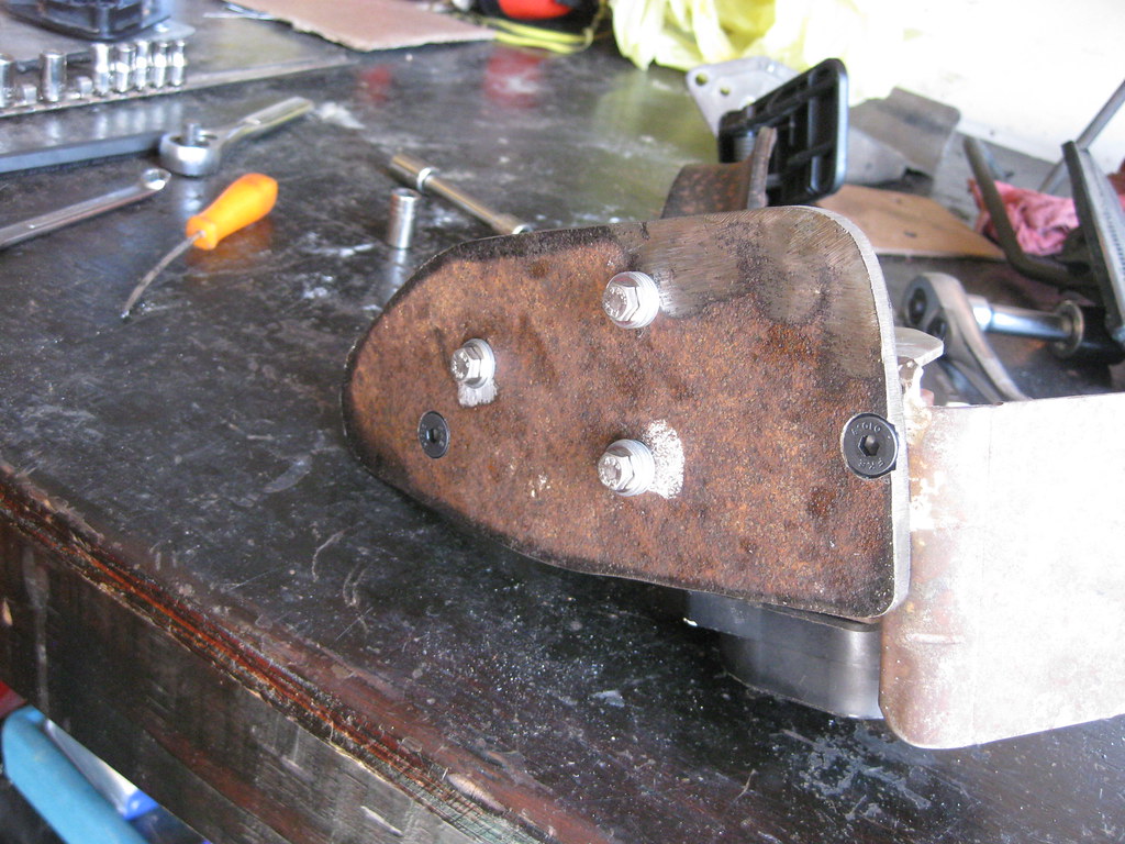
I was able to use the drill press to drill the right depth without going too far. The 1/4 inch steel gave me enough material to achieve this.
Everything mounted up as planned.
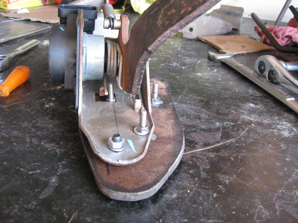
And there was no interference with the pedal travel.
The silver bolts will be on the outside of the firewall when the assembly is mounted.
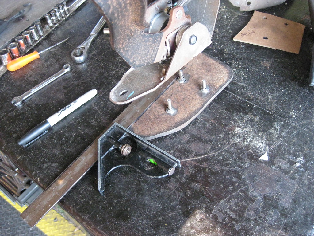
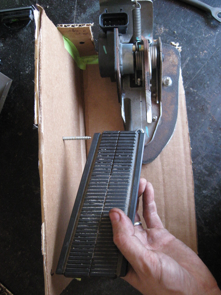
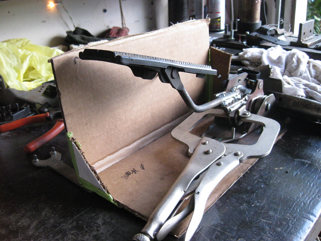
Then it was time to relocate the pedal. I made this jig to help me put the new pedal in the right place.
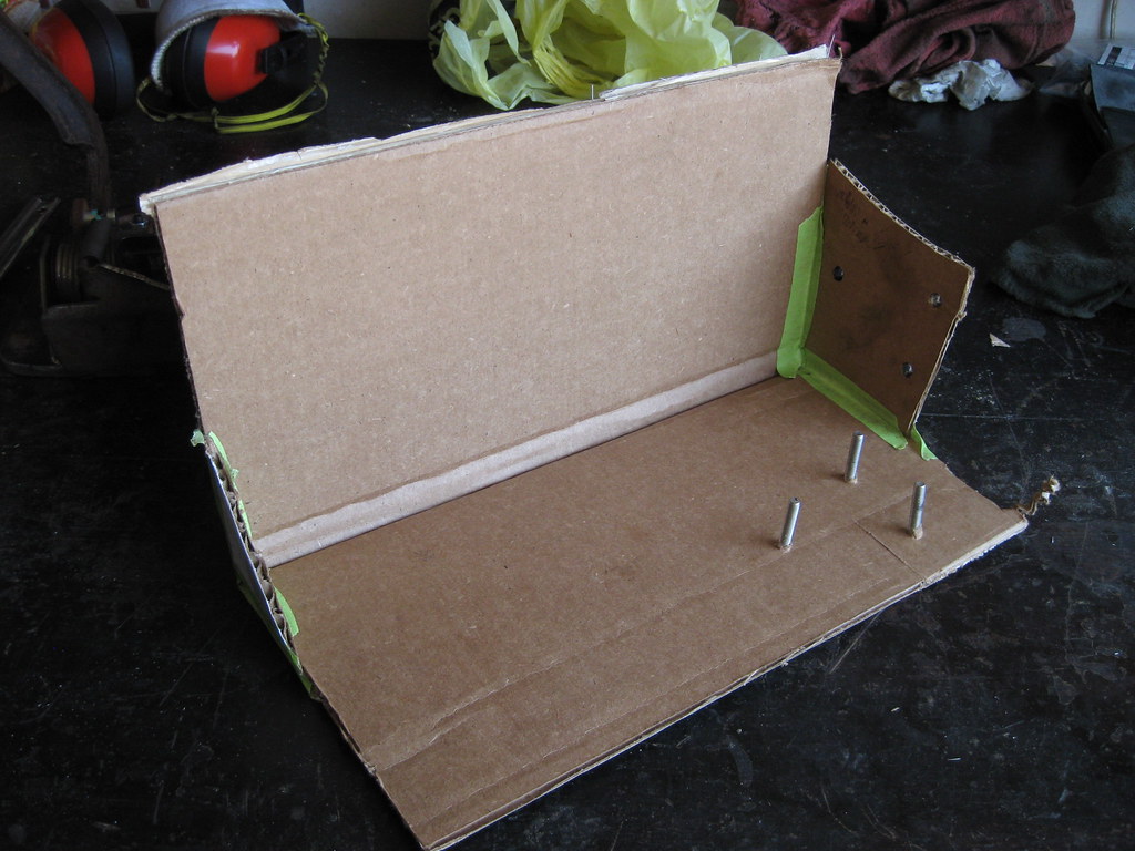
I mounted the original assembly to the jig and marked where the pedal sat.
I used a drywall screw through the cardboard to locate the depth and height of the top of the pedal,
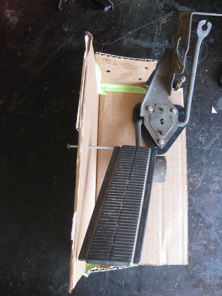
I mounted the assembly so that the bottom of the pedal aligned at the cardboard and I then marked that location on the cardboard.
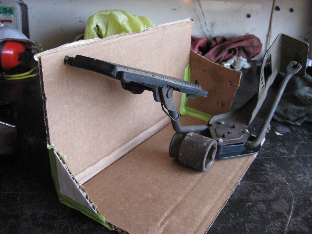
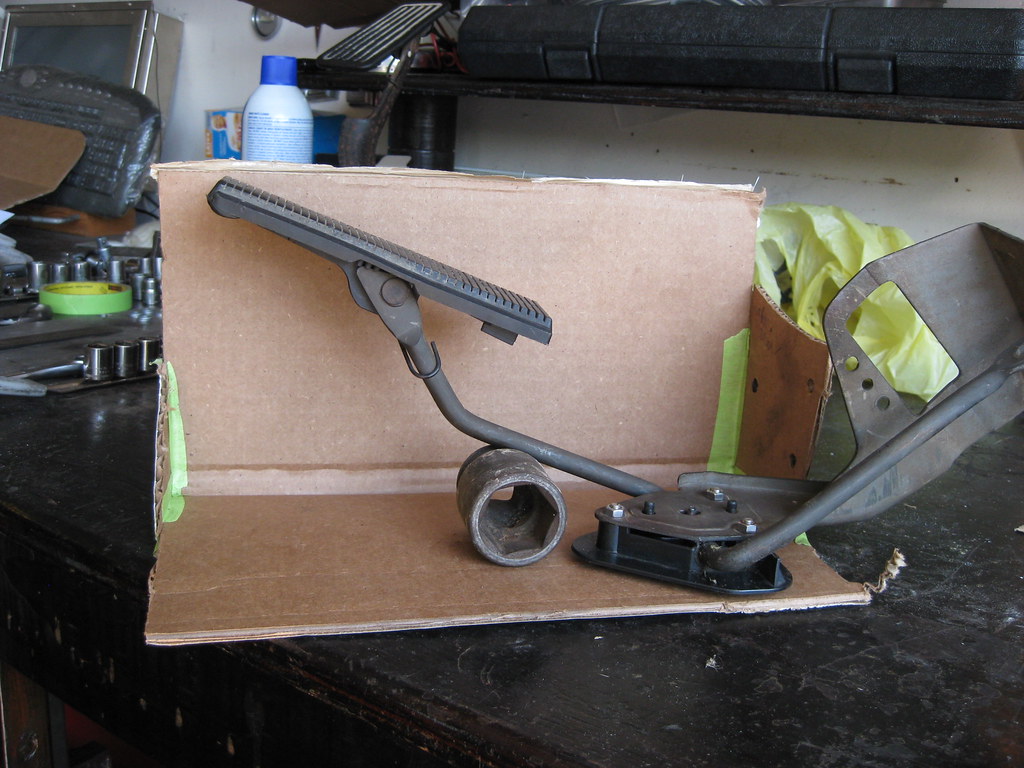
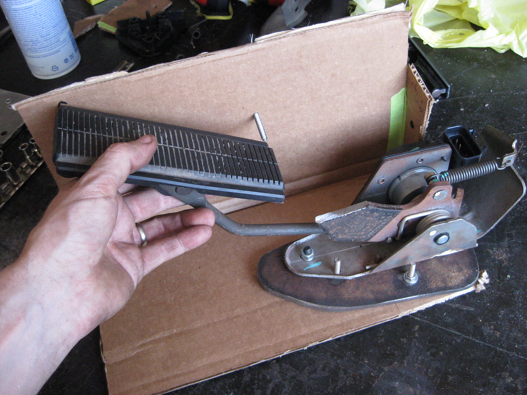
Since the new pedal assembly will use the original holes I was able to mount the new pedal assembly to the same jig and reference the marked position of the old pedal. I drew a line on the new pedal arm for the cut.
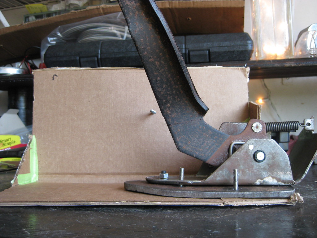
And I chopped it off with my dwindling supply of cutting wheels.
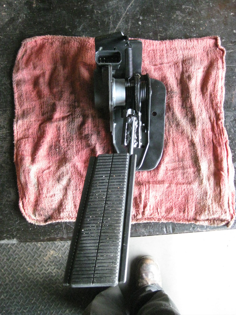
I wanted to keep the original pedal. The new pedal arm would not mount to the original pedal so I had to cut the original pedal arm and mate it to the new pedal arm. With the new pedal assembly mounted on the jig I was able to locate where the pedal should be and begin to work from there.
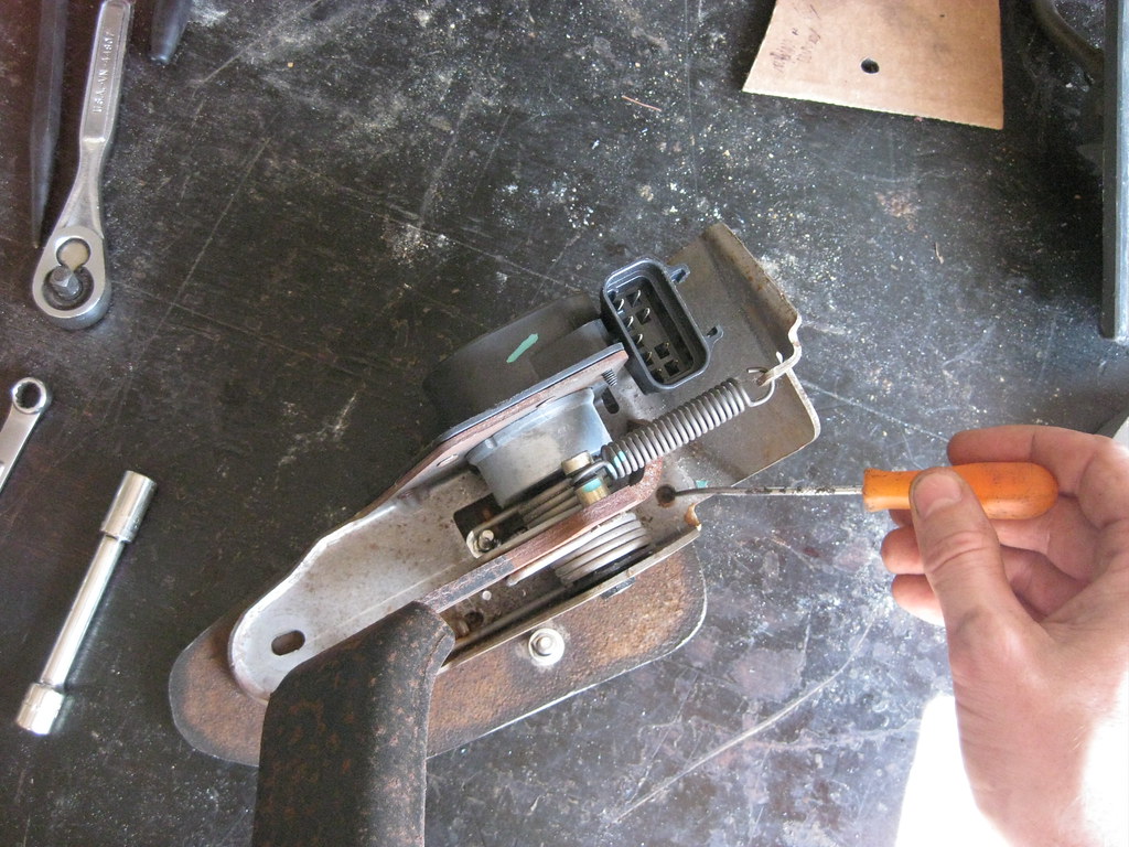
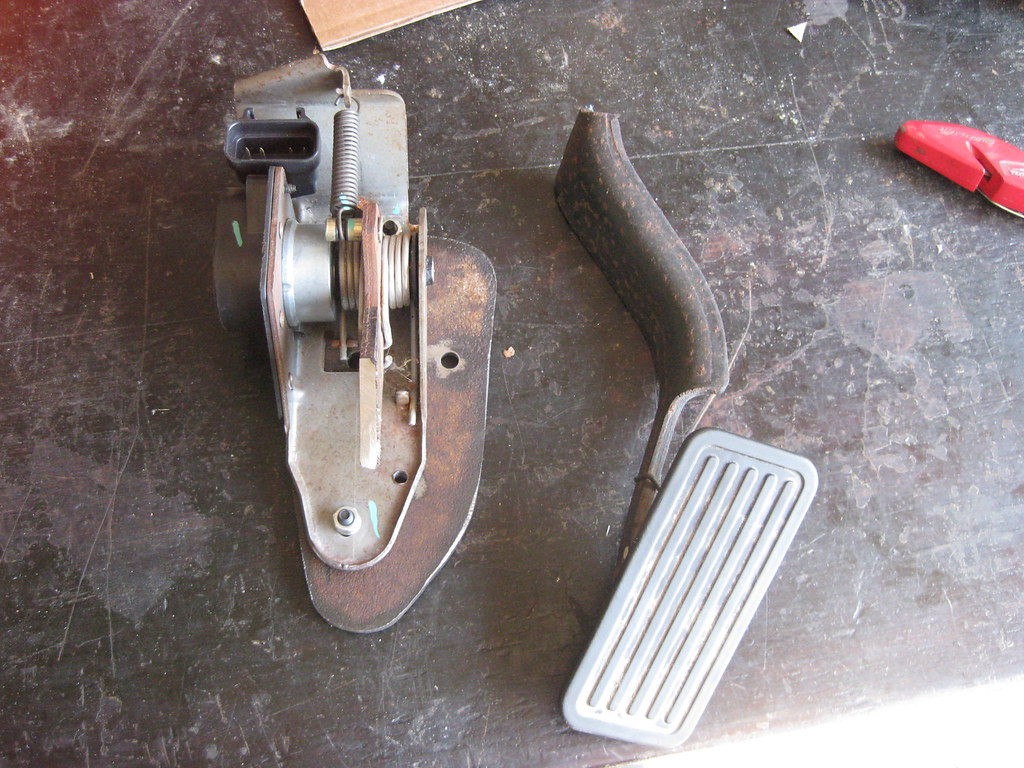
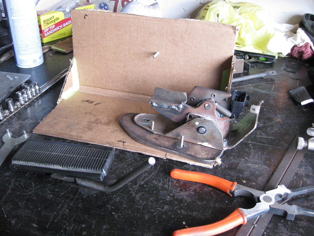
For the entire build of the car so far, this was by far the most frustrating process yet. What seems like a quick and easy process in pictures actually equates to several hours of test fits and failed ideas and bruised fingers pushing the now stubby pedal arm down with no leverage. I did take the spring off. The electronics required a special socket to remove, so I was not able to take this apart. Because of the shape of the original pedal and the way it swiveled on the arm there were certain angles which could not be modified. Because of this, no matter in what position I put the pedal it would make contact when the arm would be mashed down fully. As I stated, I literally worked on this for hours trying to get the pedal to reside in it's original location without making contact when the pedal would be pushed to the floor.
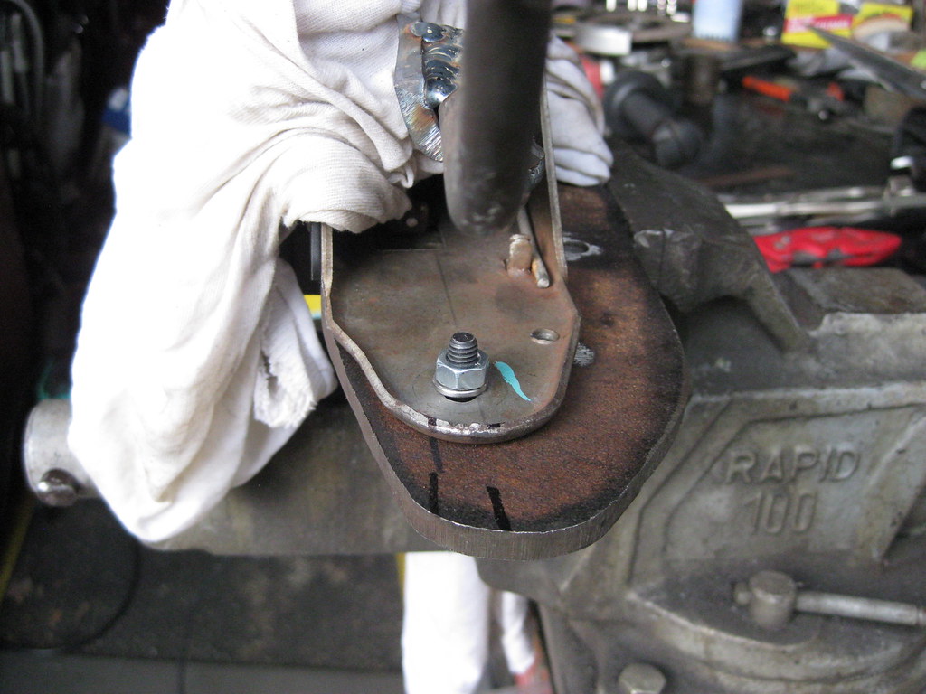
I wanted to keep the welding on the new pedal arm to a minimal to keep the heat away from the electronics. Because of this, I didn't want to cut the arm too short and then have to reweld material back on if it wasn't absolutely necessary. As a result I went through several iterations of cuts to the original pedal arm, each time cutting a little bit more at a slightly different angle until I finally found one that was as close as could be achieved. I finally reached a point where I knew this was as good as it was going to get and I would have to make this it and deal with whatever else later. I welded a plate to the original arm with wet rags and vise grips used as heat sinks attached to the arm to protect the electronics on the assembly.
I then used the pedal and arm to locate where the new arm should be welded. It wasn't very pretty, but it's on there. Again, I wanted to keep the welding and grinding down to a bare minimum.
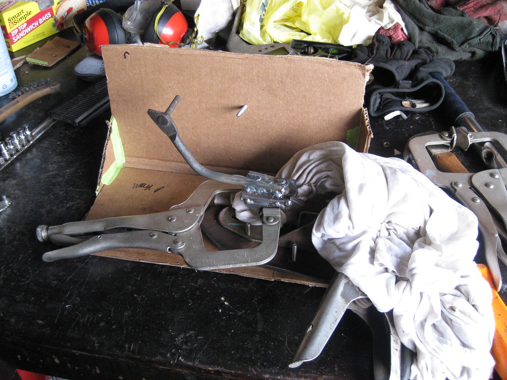
The position isn't exact but after a lot of playing with options I was able to get it relatively close.
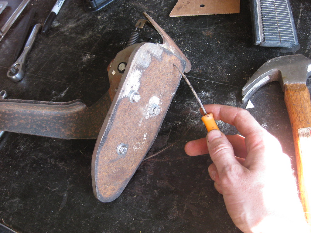
The pedal arm did end up with some interference, but it wasn't too bad compared to the previous versions.

I marked the areas and ended up cutting off the bottom of the mounting plate and using a round file to cut a relief in the bottom of the pedal assembly and taking some length off the bolt.
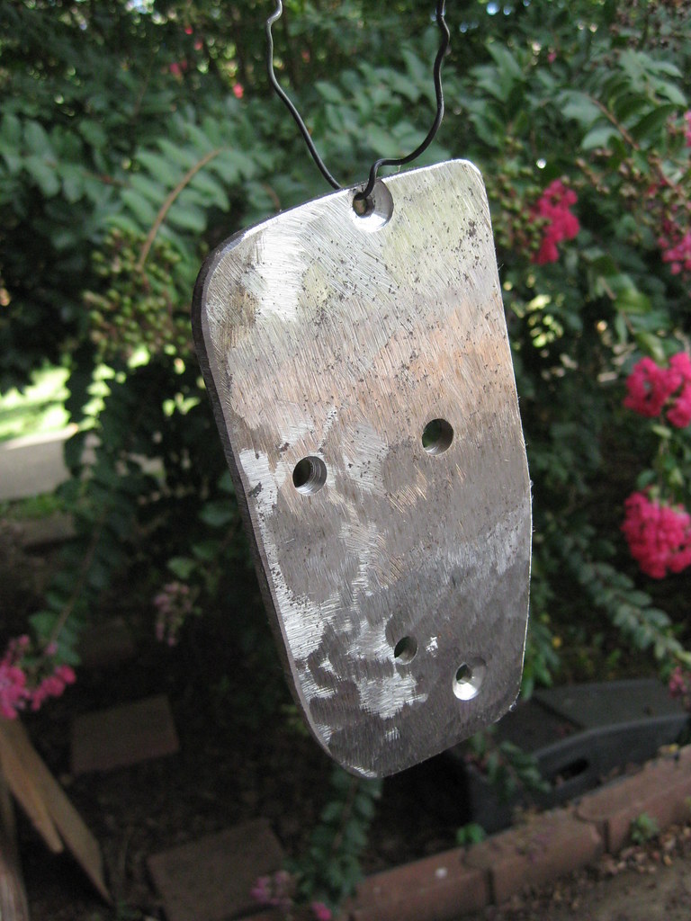
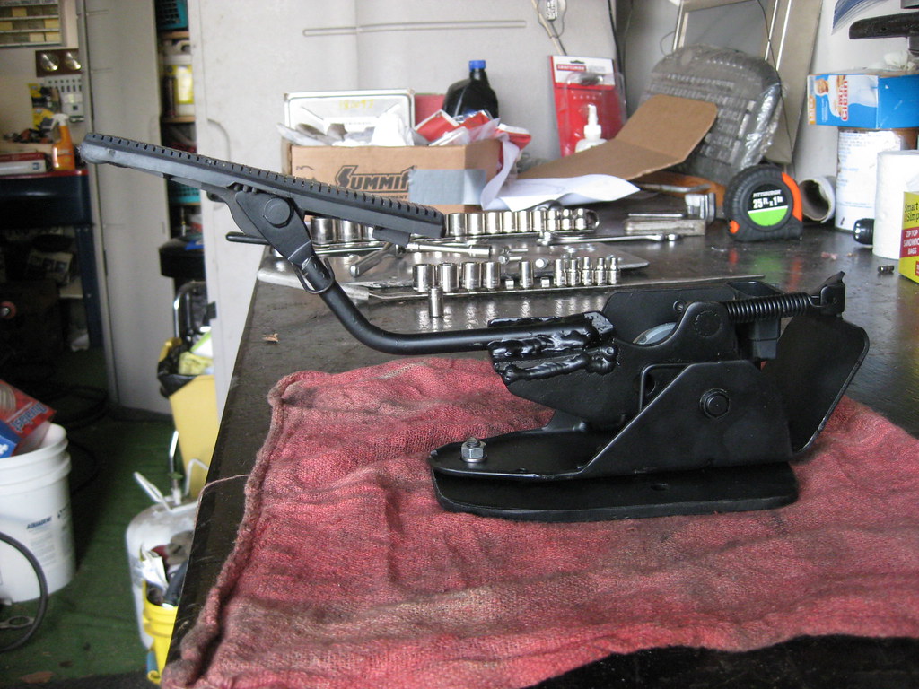
At long last the piece was ready for primer and paint. This simple piece of steel took many hours just to get to this point.
The finished assembly, after paint, bolted together.
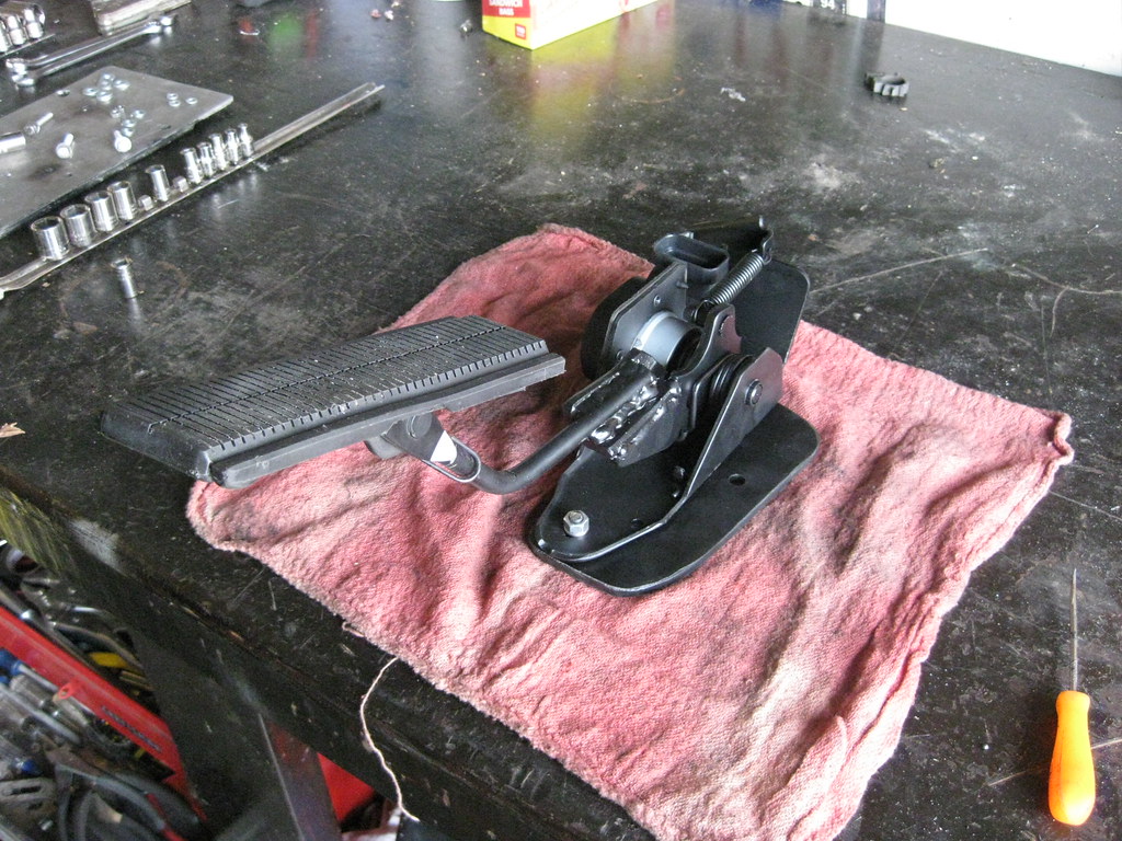
Start to finish, I probably have 16-20 hours in this assembly. Even though it looks pretty straight forward the placement of all of the pieces was so critical that finding a way to make all the parts work together in the right location was very time consuming to figure out. I understand it would have been much simpler to drill new holes in the firewall and put the pedal where it needed to be, but that's not how I wanted the finished product to be and one great thing about a project like this is you can do it however you want.
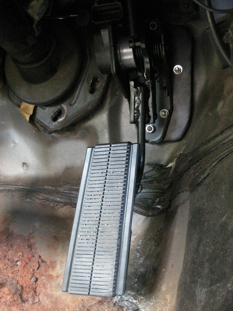
Here's the end result.
It seems to work well and allows full travel of the pedal with no interference, and I get to keep my original pedal.
The new radiator came in and fortunately even though it has a transmission cooler built in it is the same exterior depth as the radiator I returned so I was able to reuse the mounts I had previously made without modification. I glued some rubber inside the mounts and put some weight on them until it dried.
I flushed the heater core using this attachment for a garden hose I made a few years ago.
I finished up by running the heater hoses.