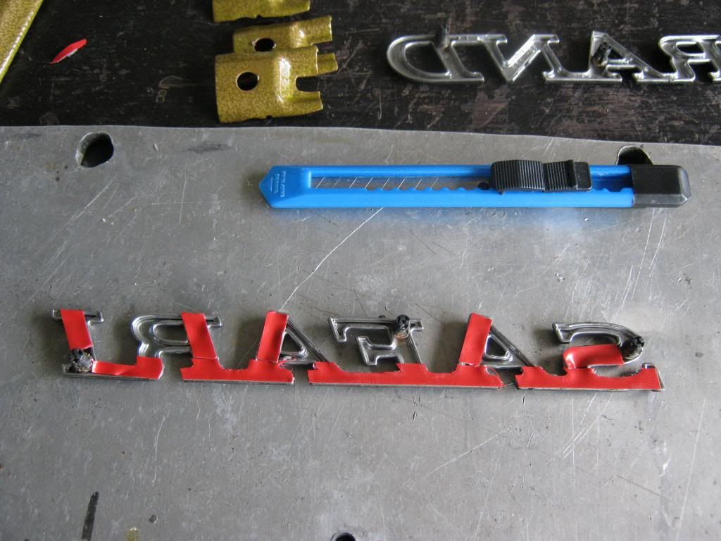
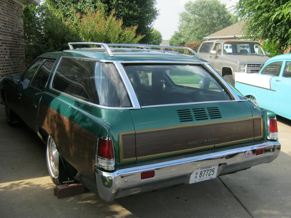
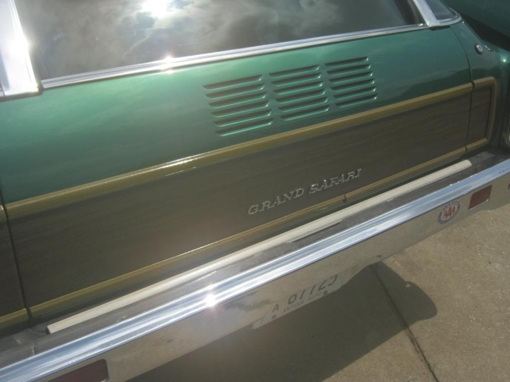
Due to missing clips and screws I have only been able to finish the tailgate so far. Earlier I had forgotten that the tailgate emblems had tabs on them, but then I realized that I thought this because I wasn't the one who took them off, April was. I watched her as she used the heat gun and peeled away an adhesive holding them on. In reality they had an adhesive as well as some press-in clips that held small tabs in place. I bought some 3M name plate adhesive strips and used an X-acto knife to trim away the extra. Finding the holes behind the woodgrain took a little bit of time but after finding one of them the others weren't too hard to locate.
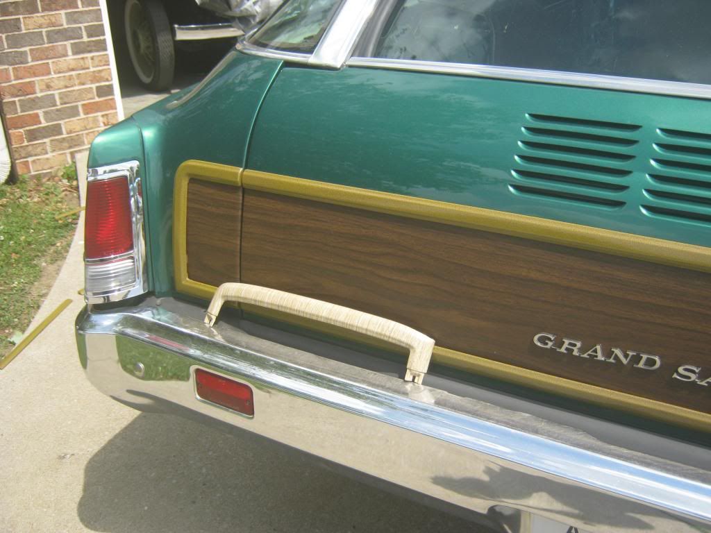
Unfortunately, during some part of the powder coating process, the bottom piece of tailgate trim broke in half. Because this is stainless steel trim I assume the trim itself must have had a weak spot in this area. When I bought the trim from a 1974 Grand Safari parts car a while back I found that not many pieces interchanged. Only the doors and one piece on the front fender would transfer over to my car, however I also found that the top and bottom center pieces of tailgate trim would interchange so I was very fortunate that I ended up having a spare example of the trim piece that broke. Also, last week I found a NOS (new old stock, an original piece in General Motors' parts stock that was never sold) rear trim piece, which was missing when we bought the car, on the internet for sale. I bid on it and got it relatively cheap. It was a very fortunate find, because these pieces are rarely able to be found, especially for a '71 or '72. Today I went back to the powder coater's to take them the spare piece that broke as well as the new piece I got from the internet. They will strip and coat them to match my other pieces, as well as finish the other pieces they lost. I'm holding out hope they find the final piece that they lost.
Here is the spare, replacement piece I have, sitting under the broken piece. It was so hot today that when I took the camera outside it instantly condensed, so a few of the following pictures are a bit blurry and the colors aren't exactly true.
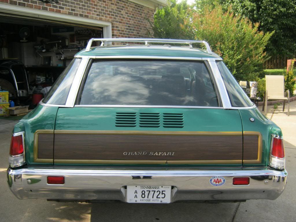
Here is the color of an original, NOS piece of trim. It was wrapped with a fake, light-colored woodgrain. Thought it doesn't show up as well in these pictures, everyone has mostly agreed the new color of the woodgrain trim looks much better with the colors of our car than the original would have. I spent a very long time at the powder coater's going through color books. This was the only color that came remotely close to looking good. At first I liked it, then when I saw the finished pieces and held one up to the car I wasn't really fond of it, but after seeing the entire rear of the car with it on in the daylight I changed my opinion again and it turned out looking very nice.
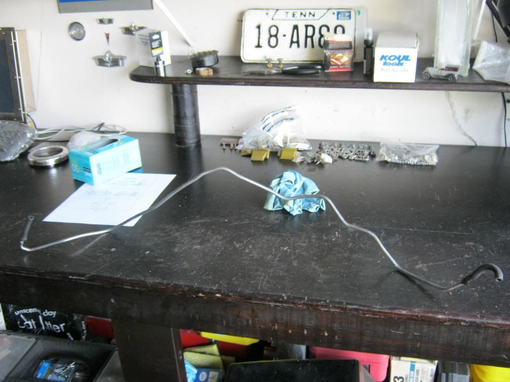
The clips I ordered for the woodgrain moldings will take about two weeks to come in. I'm looking forward to getting them on the car. Getting back to work on the transmission, I removed this vacuum line that used to go from the carburetor to the transmission, which I won't need anymore with the 700R4.
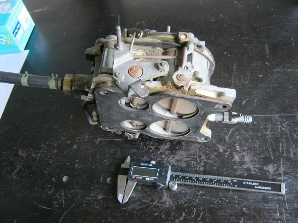
It was time to dig into the hardest part of all, handling the fabrication of the linkage for the 700R4 and achieving its correct geometry. Last week I ordered this digital caliper because the measurements must be extremely precise. Using the internet I was able to find methods of achieving the correct placement of the stud that the TV cable from the transmission will eventually attach to.
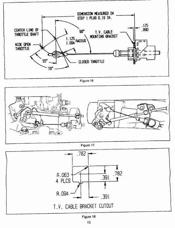
This is a copy of the page I have been using as reference for the proper geometry of the cable. In this picture, the cable is shown in a position that would be considered part-throttle. Closed and wide-open throttle are labeled, with wide open being 55 degree past the vertical 90 degrees and closed being 23 degrees (78 total minus the 55 forward) behind the vertical 90 degree mark. The distance from the center of the throttle shaft along the 23 degree line to where the hole needs to be can be between 1.125 and 1.094 inches. The rest of the diagram refers to the appropriate distance between the TV cable mount and the end of the cable, but since I am using an adjustable, universal cable, I don't have to concern myself with that part.
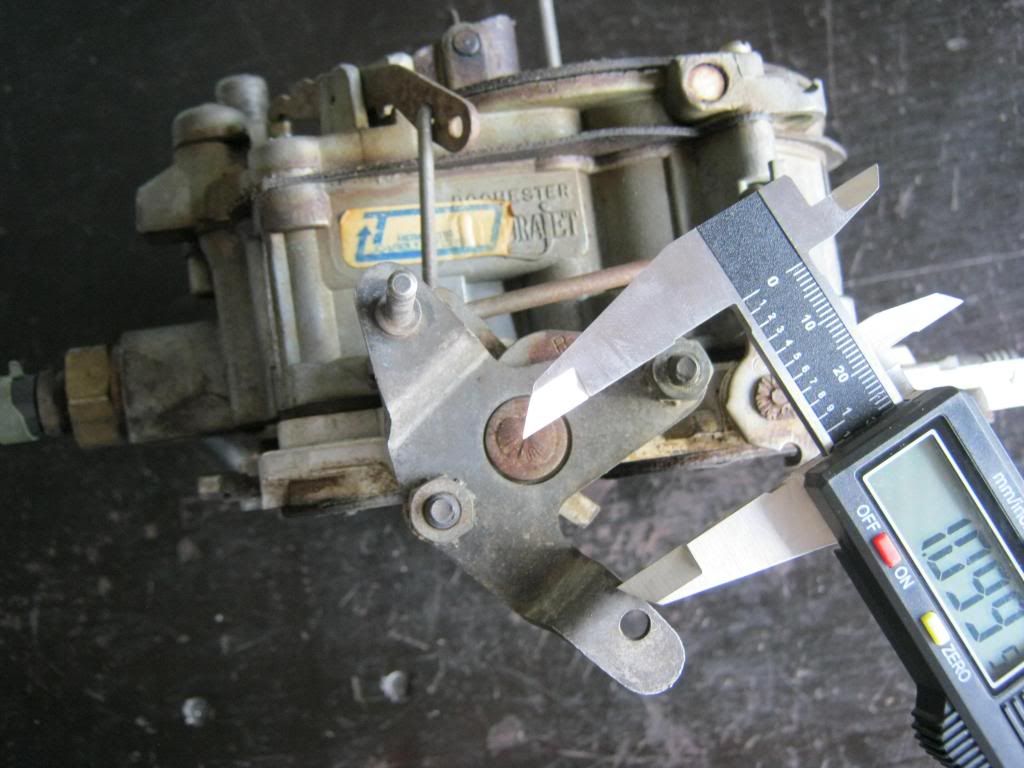
Before I begin any of the precision work I need to get a general idea of where the new hole will need to be. Since I knew the placement of the new hole would be slightly beyond the boundaries of the current arm I knew I would need to weld on new material, but I needed to know approximately how much and what shape. There is a tolerance of a few thousandths of an inch within the length of the hole from the center of the throttle shaft. There is a small indentation in the center of the throttle shaft but I double checked it with the caliper to ensure it was, in fact, the true center of the shaft. I could see that the hole would be slightly closer to the shaft than the existing one.
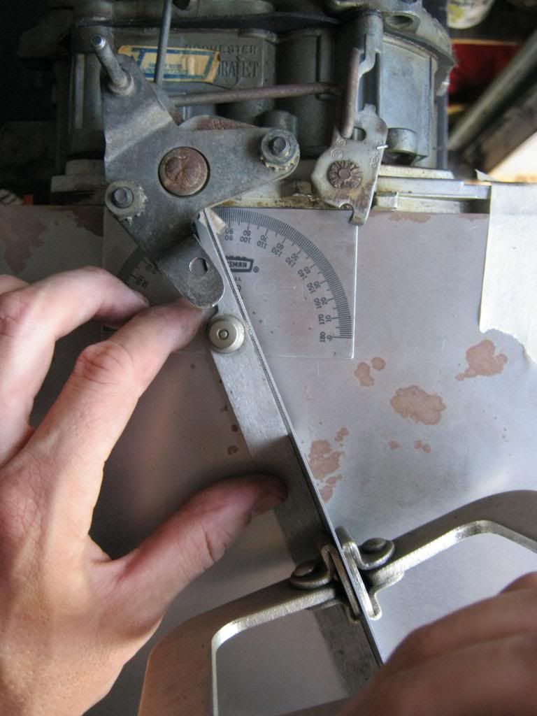
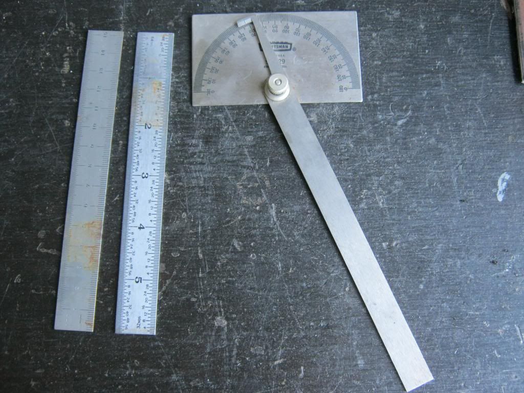
I didn't have a protractor and I was afraid that a simple, plastic one from the store may not have been exact enough for my needs. I went to my neighbor's house and he let me borrow two good straight edges and an angle finder.
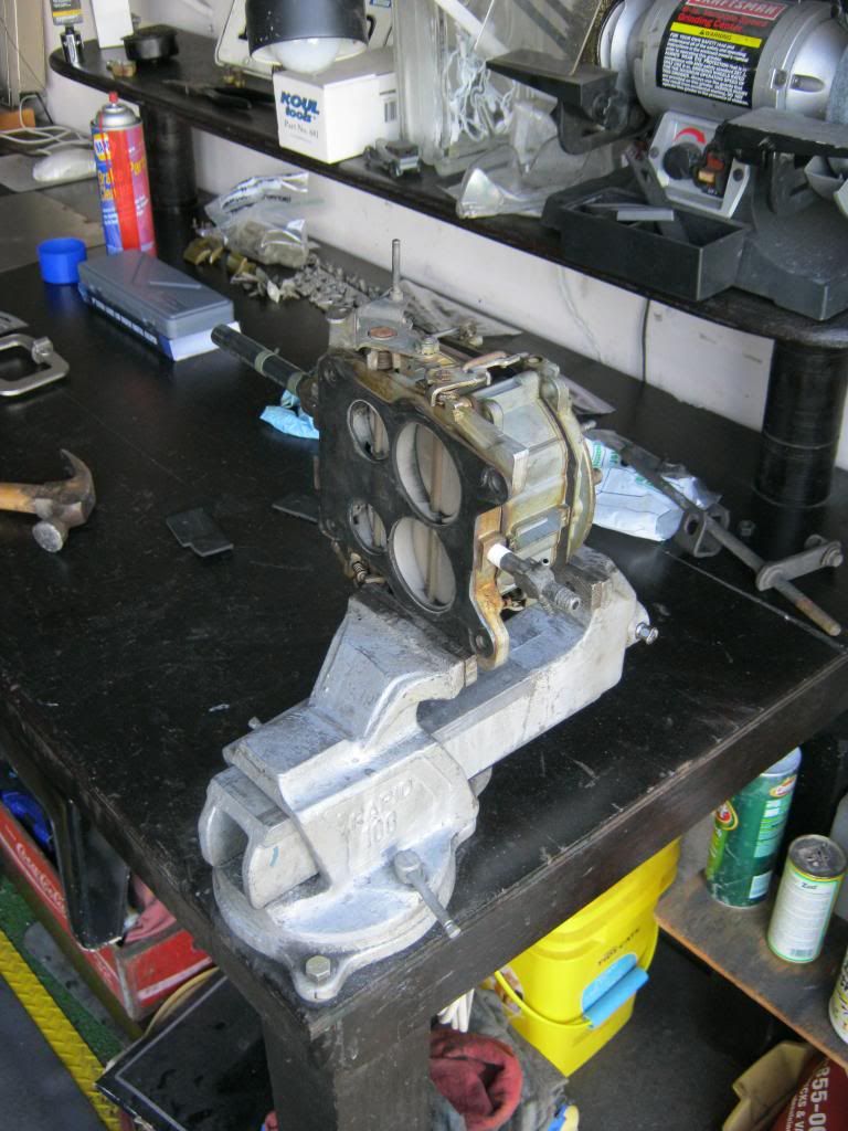
It took me a while to come up with a working method to achieve everything that I would have to do. I eventually came up with a plan that started with me unscrewing my vise and turning it around 180 degrees and getting the carburetor mounted in the vice relatively close to level as well as allowing the full range of motor of the the throttle shaft and butterflies.
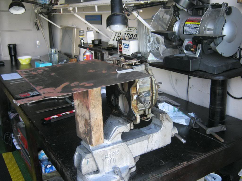
Then I placed a flat surface with a straight edge against the straight edge of the bottom of the carburetor. I was fortunate to find the exact right length of wood to allow a flat surface. This will serve as my flat surface for the angles I will later draw out as reference on a piece of paper. This is a temporary setup, but later I will need to secure them in place.
If you imagine a vertical line going through the middle of the throttle shaft and extending straight down, perpendicular to the imaginary horizontal line of the base of the carburetor, you would then use that vertical line as a guide to determine your angles. Since this vertical line is 90 degree (perpendicular) to the base plate of the carburetor, I will call it the "vertical 90 degree line." The hole needs to be 23 degrees to the right of the imaginary 90 degree vertical line. This gives it a total of 113 degrees, so that is what I set my dial to.
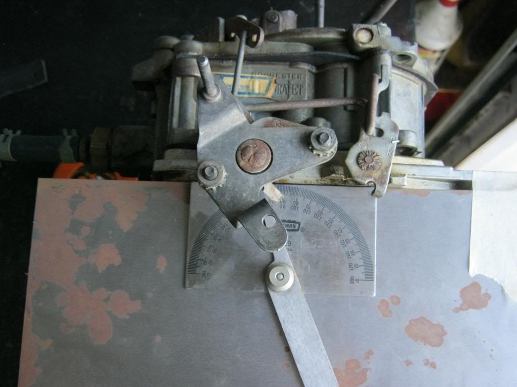
I then clamped two straight edges together, one on top of the other and with one extending past the other. I held these flush against the 23 degree angle and while keeping the top plate of the angle finder even against the base of the carburetor, moved it until the straight edges lined up exactly with the center of the throttle shaft.
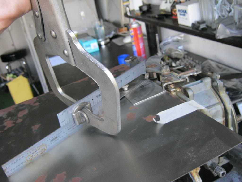
It is along this line that the new hole will need to be made. Though I don't need to know exactly where at this time, I do know it will be somewhere slightly above the existing hole. This information will give me a good enough idea of where to weld on the extra material. I determined I need to add about 1/8" to the top and 1/2" to the right of the existing hole, just to be safe and give myself plenty of material to drill. I can then shape it later and remove any excess.