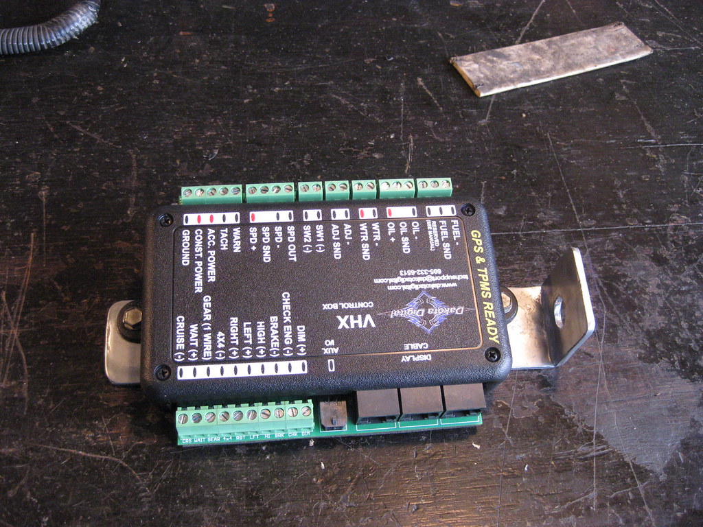
I have a lot of extra spray paint cans that I rarely use taking up some much needed space in the cabinet. That means the bracket for the Dakota Digital box that will be tucked up way under the dash and never seen will be..... chrome. There's still a shifter linkage bracket on The Camaro that's bright gold that no one will ever see.
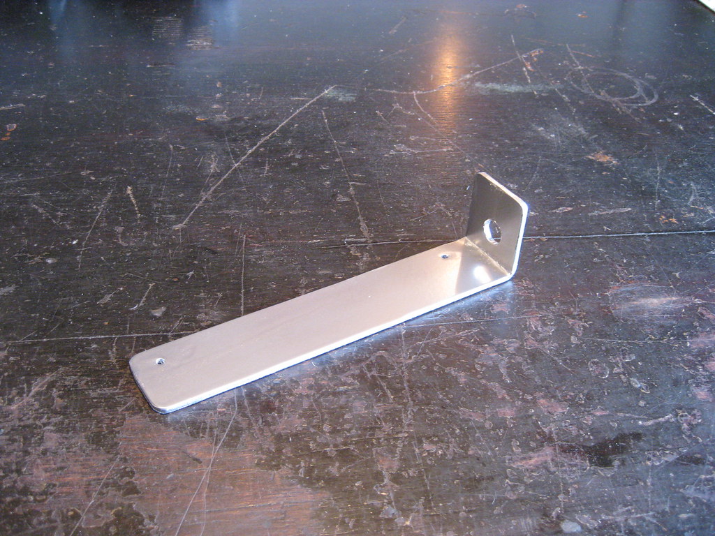
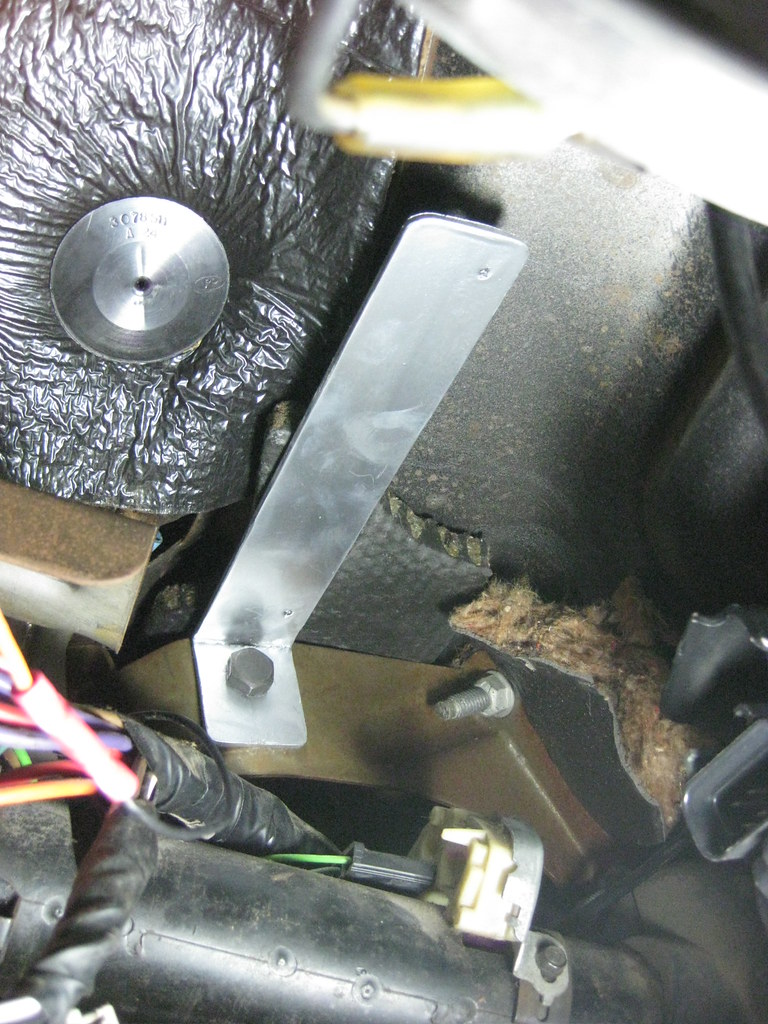
I used the bolt for the brake pedal arm to locate the mount. The Dakota controller will mount here, over the top of the steering column. It's also close proximity to the hole in the firewall so the wires won't have to be very long.
Next I mounted the electronic pedal controller. There was a good place to mount it on a bracket that was already in place. After finding a good place for it to sit I made a template out of cardboard.

And marked where to drill the holes. Fortunately, the drill easily fit into these locations.
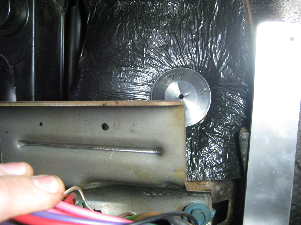
The pedal controller box originally mounted under the hood on the Avalanche. I'm mounting the box inside, so it will plug into the pedal and go straight to the box. I removed the old firewall grommet, which could seemingly double as an escape hatch on the Avalanche.
I thought I was going to have to make a trip to the hardware store to get some self tapping screws and then The Caprice provided two screws exactly the right size, and they were self tapping, right there in the glove box as I cleaned it out to find a place to mount the OBD connectors. It seems after all this time she's finally come around to being cooperative on this build. I used them two mount the Dakota controller to the mount.
I think this ground strap broke during the engine installation. I'm going to reattach it to the body where it goes.
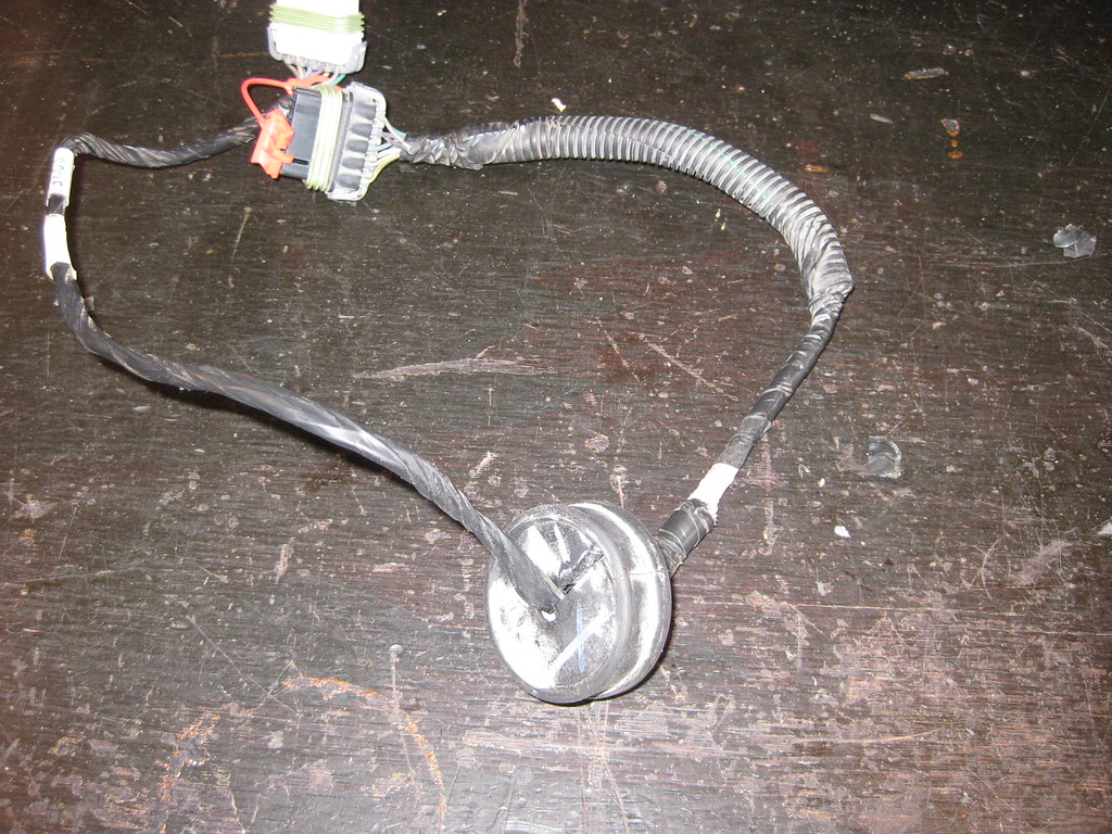
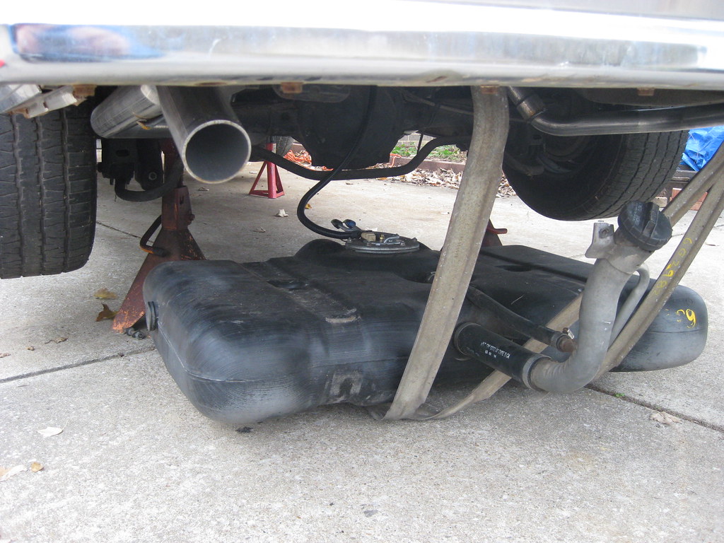
I dropped the gas tank to install the fuel pump and sender harness. Hopefully, this will be the last time I have to install the tank.
I hooked everything up except for the fuel tank vent, which I am still considering as to what route I want to take there.
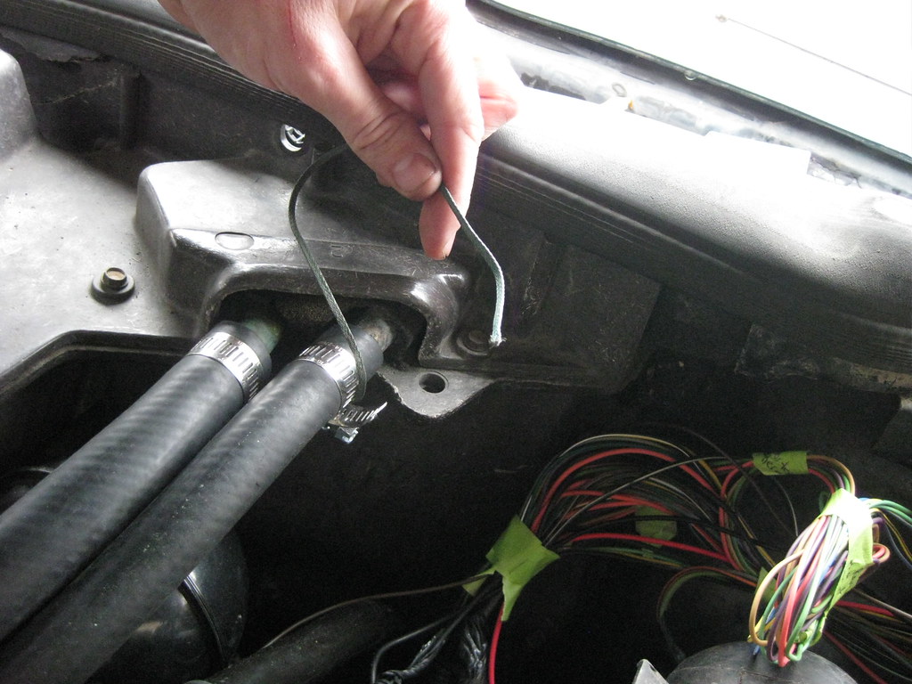
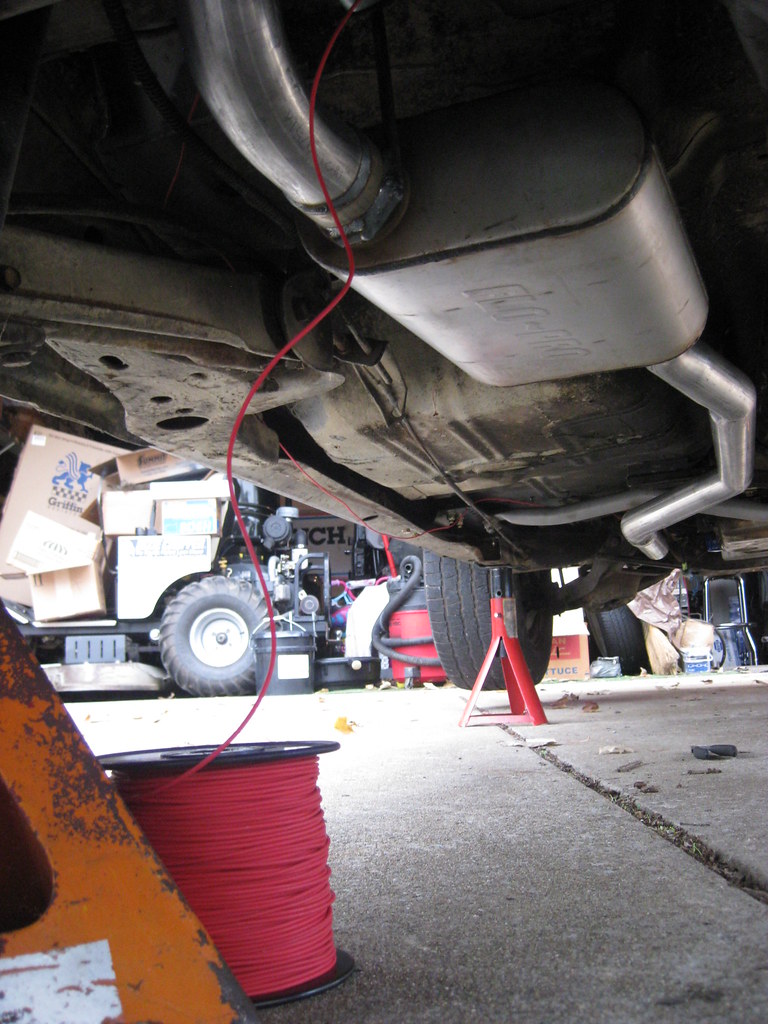
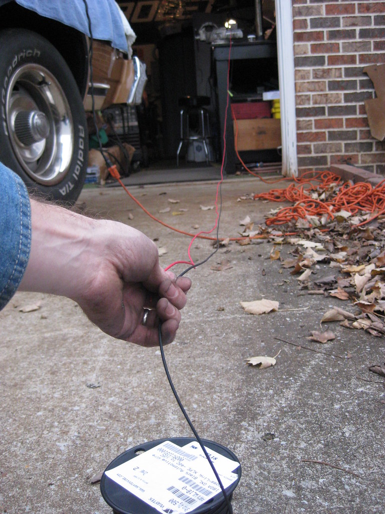
I used a single wire to measure how long all of the wires would need to be to run back to the fuel pump harness, finding a good path down the frame rail and up to the fuse box. It was time consuming installing and uninstalling and using green tape to make notes about where wire loom and connectors should go.
Then I cut the other wires to fit.
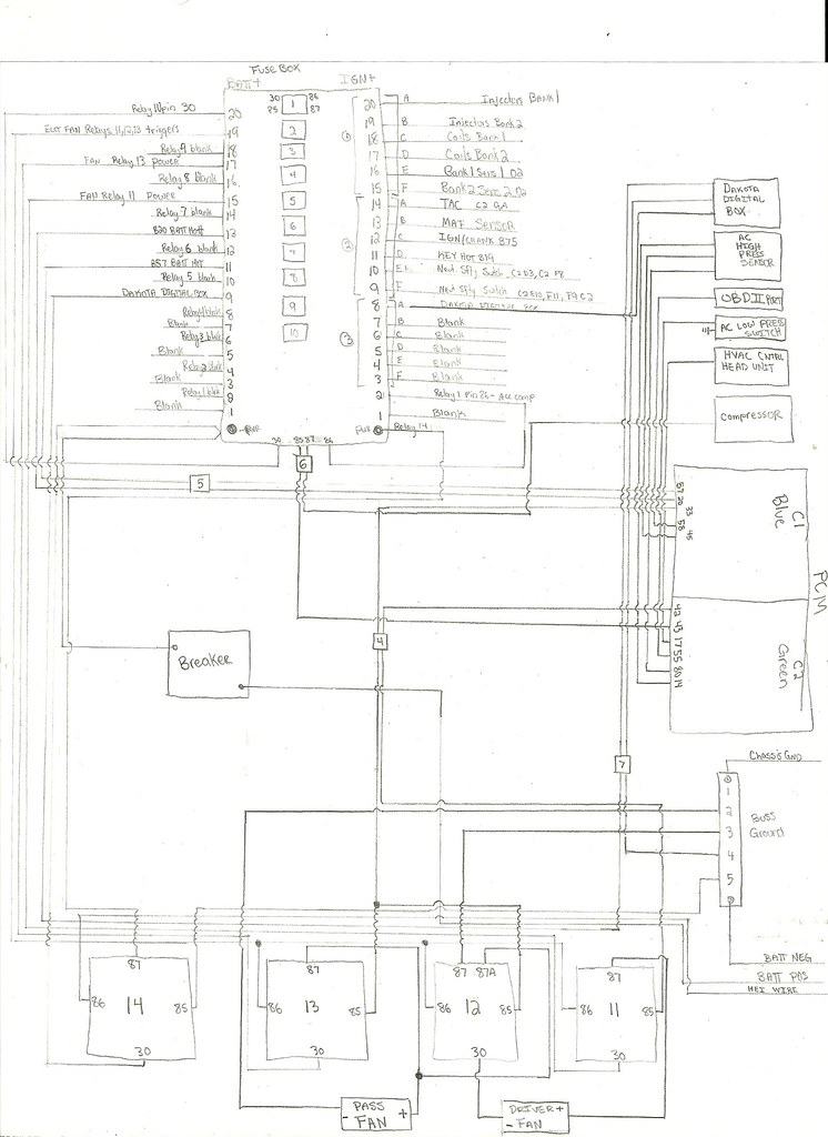
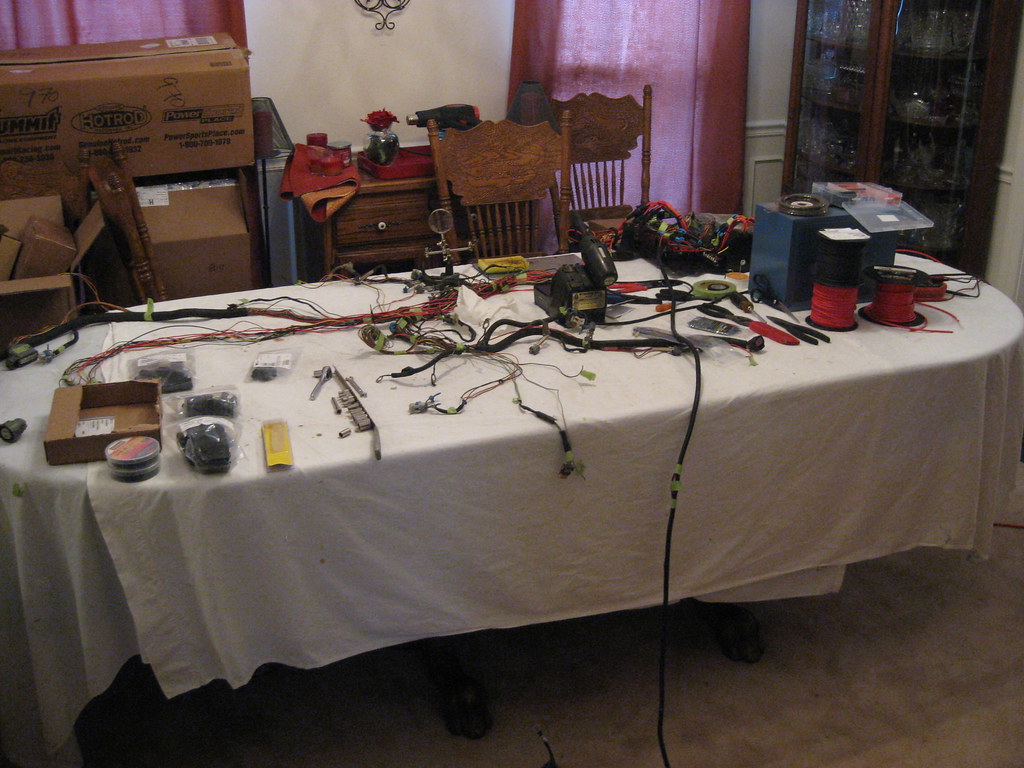
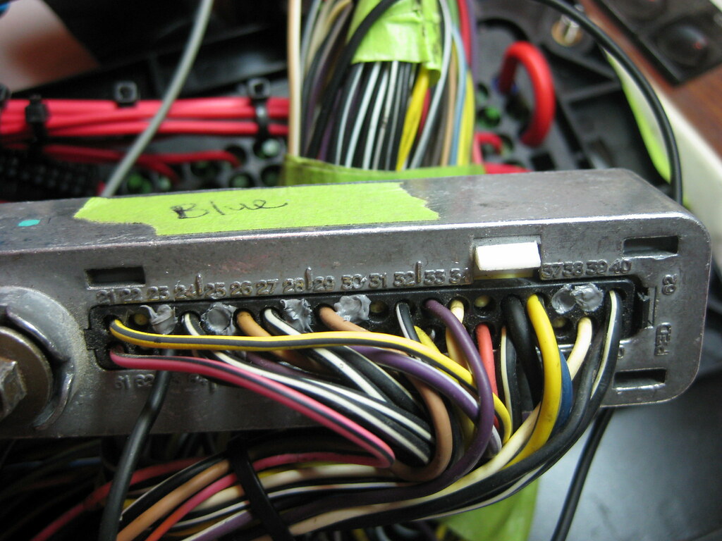
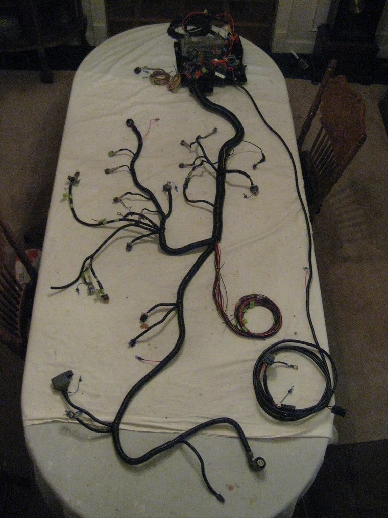
Then it was time to test fit the harness. I had, at long, long last, finished up everything on the harness I could without putting it in the car and measure how long some of the wires needed to be. I used green tape to mark where the wires would need to exit the loom so when I wrapped it in black tape they would be in the correct location. I ended up using just a few long wires and then marking them with green tape to indicate how long certain wires would need to be, then when I took the harness back inside I would measure a new wire the length it needed to be with where I had marked with tape on the test wire. For example, I had a mark to indicate how long it would be from the PCM connector, inside the cabin to the Dakota Box, or OBD connector, or how long to the AC components, etc, following the loom.

Then I once again made base camp back in the dining room.
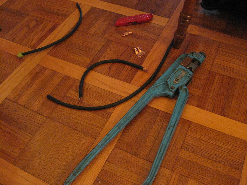
I had a pretty frustrating time at the local electric shop. I had measured exactly how many and how long I needed each wire to be for the battery and ground wires. In a story that's too complicated to explain, I ended up having to cut my own lengths with tin snips and I pieced together enough of the correct size lugs from several different stores to complete this part of the project.

I had to rent this tool to crimp the lugs on the wires. This tool and I spent some time together a few years ago when I had to rewire my lawn mower.
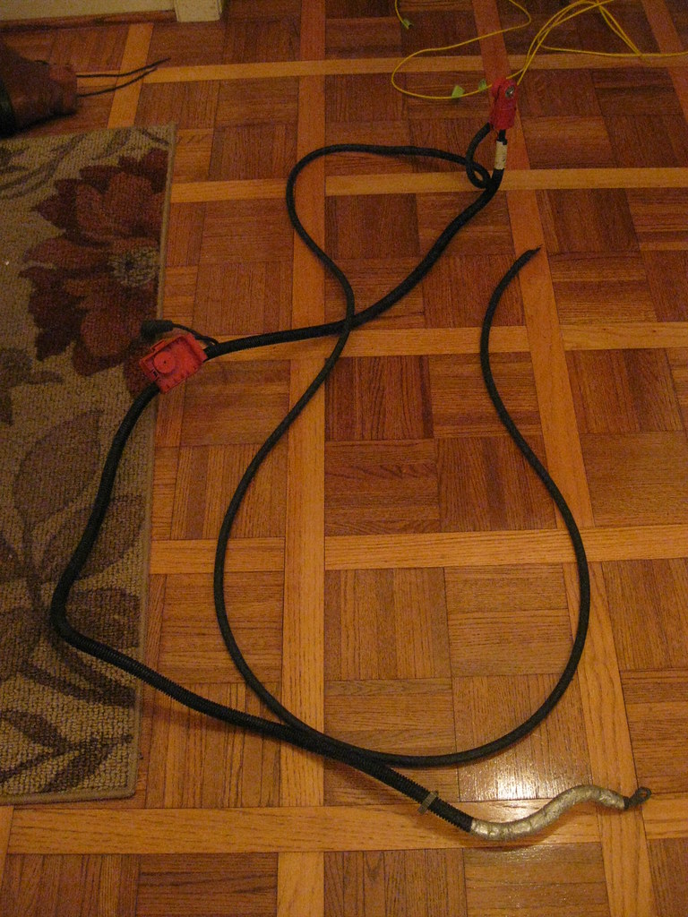
The original battery cable had a lead coming off of it that went to the fuse box. I spliced the wire with a huge barrel connector and crimped it with the rented crimper and extended it to reach the fuse box. All the connectors got heat shrink tubing.
The original unused ports on the PCM connectors had rubber stoppers in them. I used RTV to cover the holes to prevent moisture and dirt from getting inside for the slots where I removed wires from the harness.
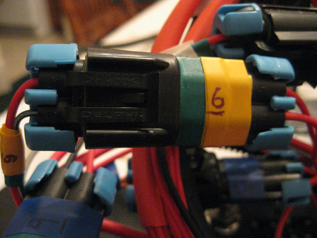
I finished up all of the electric fan wiring and various components and connectors so everything can easily come part if ever need be. I then color coded all of the connectors on the fuse box so if I ever take them off I can tell which ones go back together. Green and yellow goes with green and yellow. Hopefully even I can figure that out later down the road.
After what seemed like endless soldering, the harness was finally done.... almost. I actually rubbed my hands raw from installing the looms.
There were a couple spots where I didn't exit the wires in the correct location on the harness and I had to cut the tape off. One was the alternator and temp sender wires.
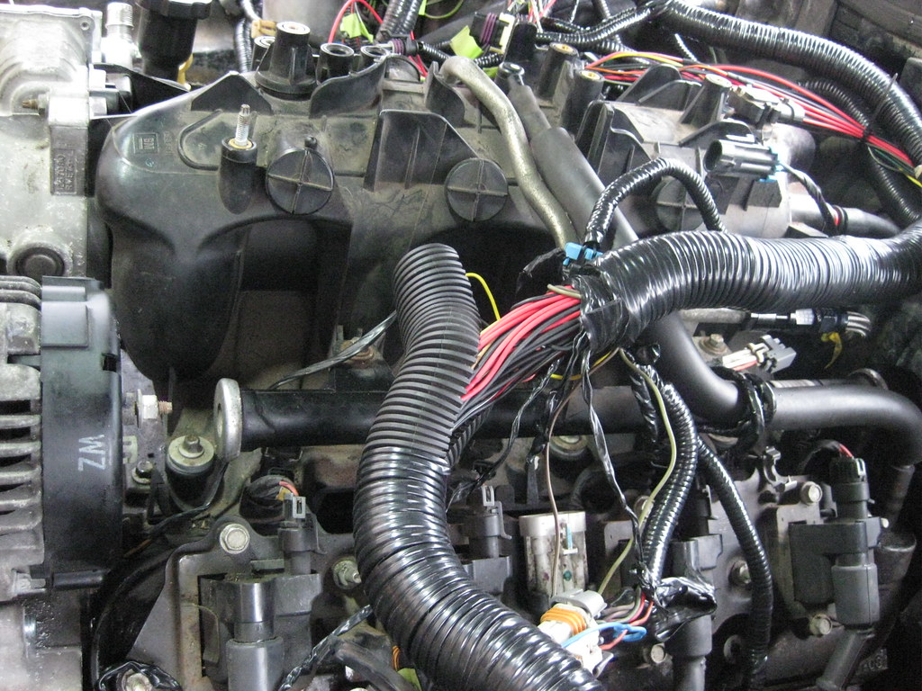
The other was the MAP sensor. It was too short and didn't let the harness drop down far enough behind the engine. I exited the wires and wrapped everything back up.
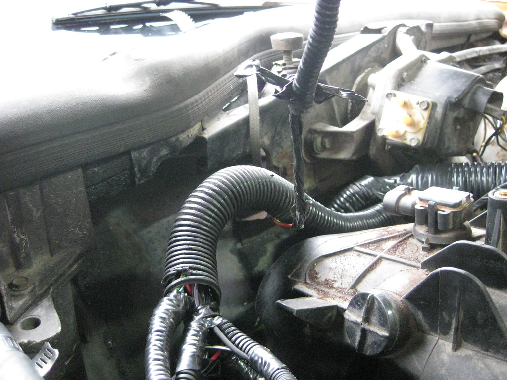
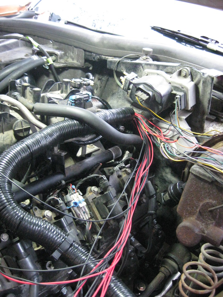
Next I ran all the wires through the firewall. This was very frustrating. I had already installed the grommet and I installed each wire one at a time through it into the cabin. The last few wires were very difficult to get through. When I was done I needed some slack on the engine side so I tried to hold the grommet and pull the wires out just a little. This caused the grommet to pull out of the firewall. Then I had to try to install the grommet with the wires already through it. I got it installed, but had I known I was going to end up doing that I could have just run the wires through the big hole in the firewall and saved myself the trouble of doing them one at a time.
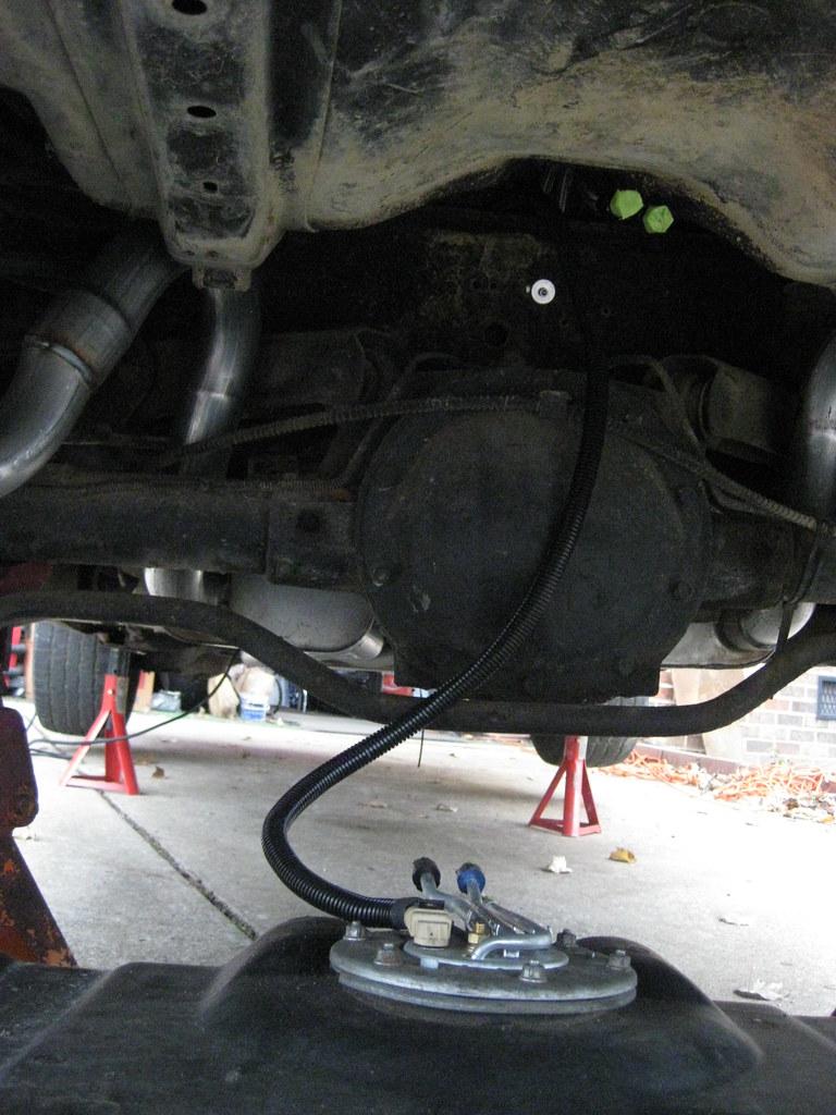
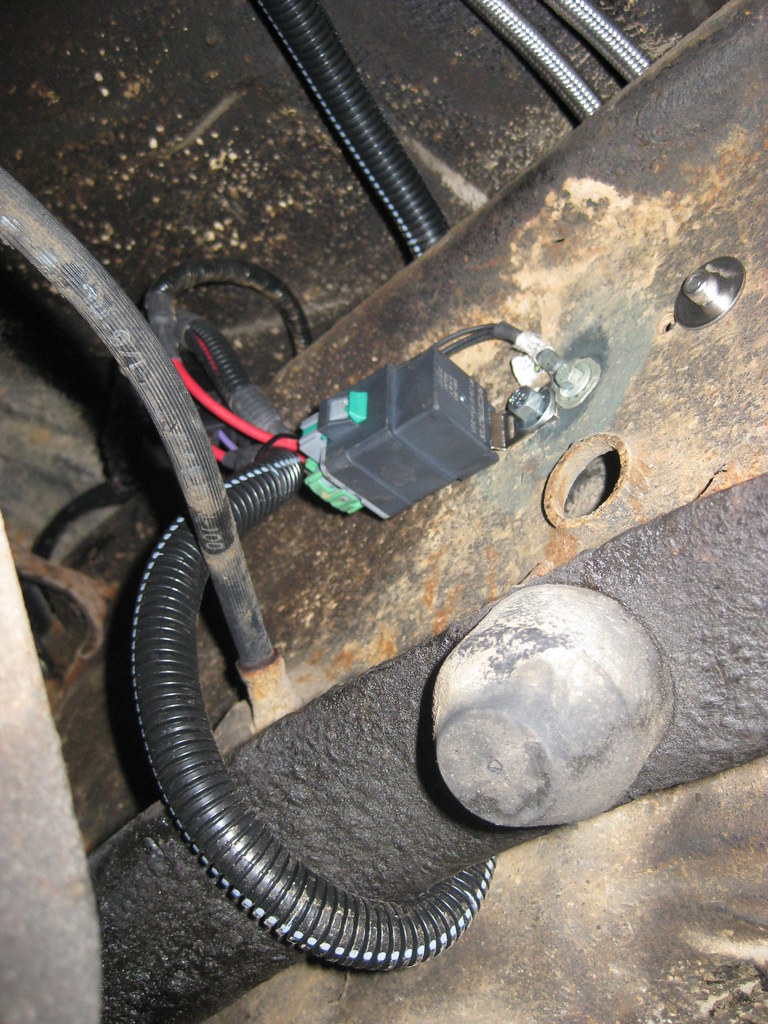
Next I installed the fuel pump relay and harness. I cleaned the frame to bare metal and installed the ground wire, then covered it with primer.
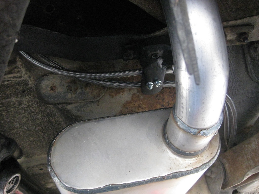
Here's the routing of the fuel line with the new exhaust.
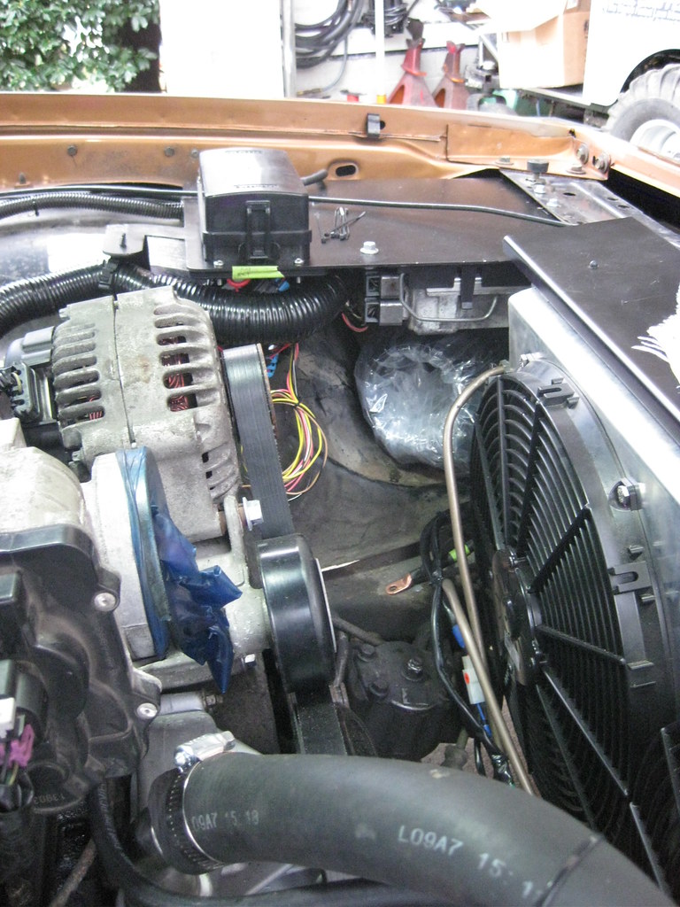
LS engines are very sensitive to air temperatures. Installing a filter directly behind the radiator would cause the filter to suck in all the hot air. My plan was to have the air filter, pictured below wrapped in plastic, to sit under the fuse and PCM panel, and then to eventually seal the side of the panel to make a cold air intake. I'm curious how much heat the PCM will put off.
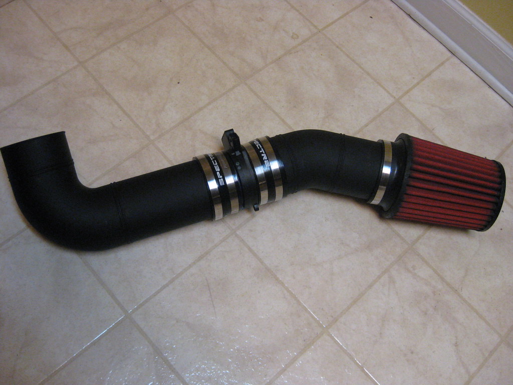
After a lot of research I found all the components I would need to make the air intake. I ordered this universal kit made of a thick plastic. My goal was to have as few connectors as possible. I did not have a way to hold the tubing while making cuts so Dad came over and helped hold the tube while I cut it with a sawzall. I've seen where other people have used super glue to put their pieces together and had good success, but fortunately I didn't have to glue any pieces together because all the joints were to couplers.
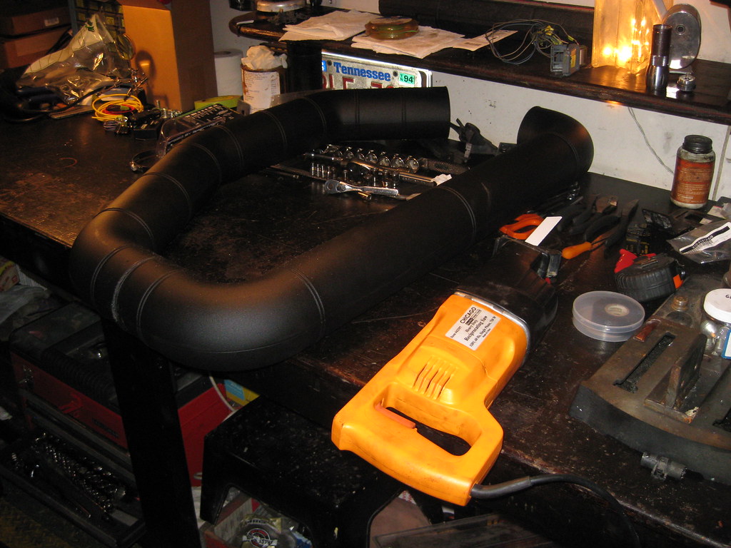
The finished piece has two bends and a non-oiled filter. From what I have read there is a potential for oiled filter to cause issues with the MAF sensor. The MAF sensor is installed in the middle. I would liked to have installed the MAF directly behind the filter so that I could hide it. I did a lot of reading about MAF sensor placement and there are many opinions on this topic. The general consensus seems to be that though the MAF will work located almost anywhere along the tube, it performs best at least 6-12 away from the throttle body and is best if away from the air filter as well. It should be in a straight stretch if possible and not directly behind a bend. The best placement for my choice would have been directly behind the small bend because this would have put it close to the fuse panel so the wires would have been very short, and it also would have kept the MAF further away from the alternator and belt assembly. As it is now, this MAF location was the best for optimal operation of the sensor so that's what I chose. It's close proximity to the belt will mean that I may have to place the MAF pointing up, so that the wires are exposed. I would have preferred to point them down to hide them, but this car will be a daily driver for, hopefully, many years, and for this build proper engine performance takes precedence over aesthetics in areas like this. I will also need to add a brace to support the filter end of the intake.
The kids have been at their grandparents this week and I've been able to come straight home and get some things done like some ground straps, installing the original car's harness for the starter and things like that. It's dark when I get home and the temperatures have been in the 20s so I haven't been taking pictures.