Another bout of weather and sicknesses in the household prolonged progress yet again. I also had to divert some attention to some issues with the Lumina which had to be fixed.
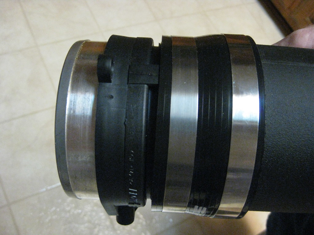
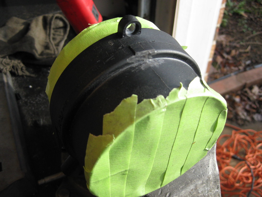
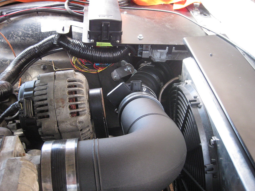
There was a plastic tab on the mass air flow senor that apparently fit into a grove to clock the sensor in the correct rotation on the original application. Here, it prevented me from clamping down the MAF sensor straight.
I used the dremel and ground the tab off.
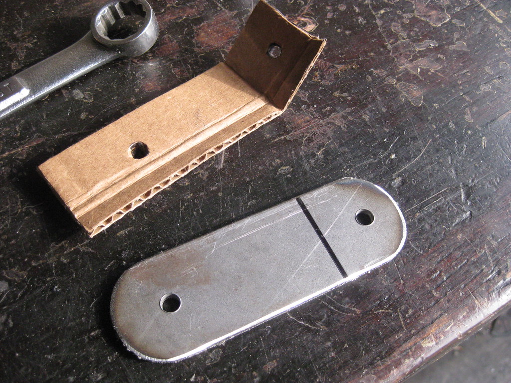
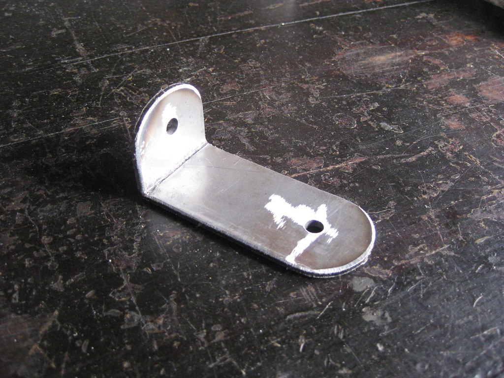
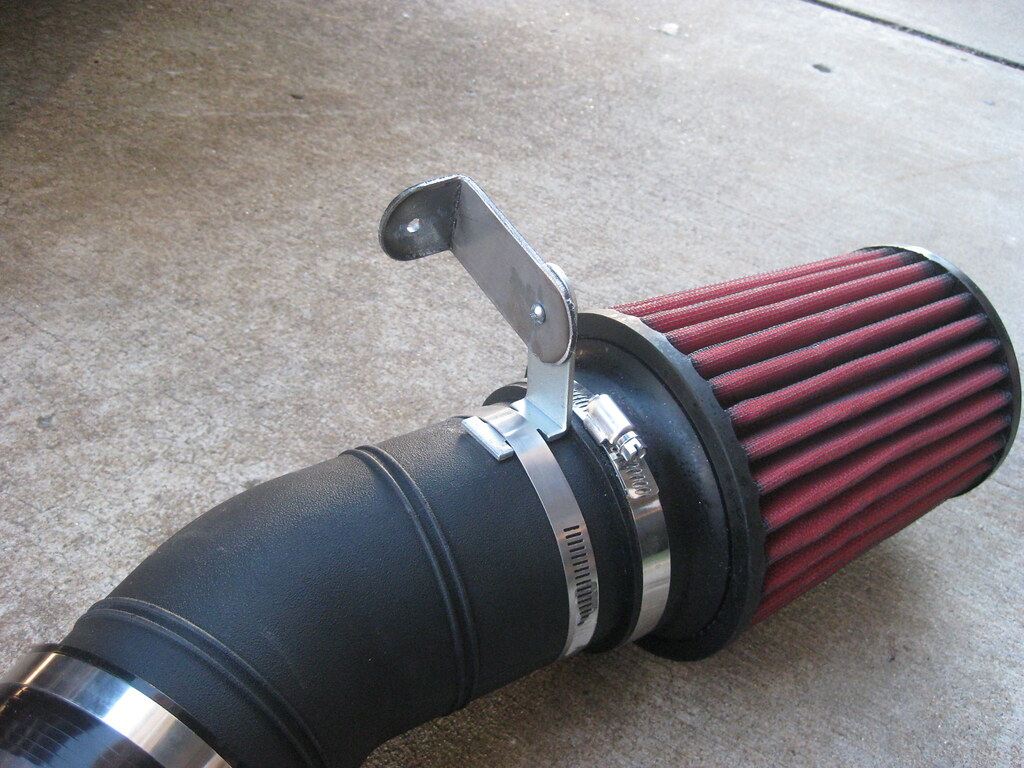
I also needed to make a bracket to support the filter end of the intake.
I remembered to drill the holes prior to bending this time.
The bracket ended up looking like this. I have yet to paint the bracket in the pictures below.
The intake setup ended up like this. The filter is positioned under the fuse and pcm panel. I later plan to block off the side of the panel to create an airbox. I need to find out how much heat the pcm put off to make sure it won't heatsoak the intake.
The day I finished up the wiring under the dash it was very, very cold. I had several layers of clothing and coveralls on, so it was really difficult to lay in the floor and reach under the dash to work with the wires. Also, the metal floorboard was so cold it would come through the layers. There was a Christmas parade that day and I wanted to be there with the girls so my workday got cut a little short.
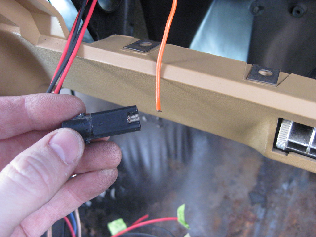
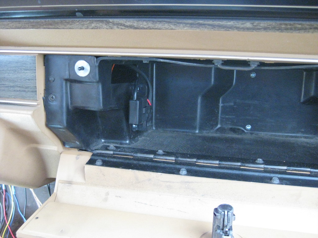
I took the glove box out so I could mount the OBDII port. The wire for the glovebox light was barely hanging on and it broke off when I removed it so I soldered it back in place.
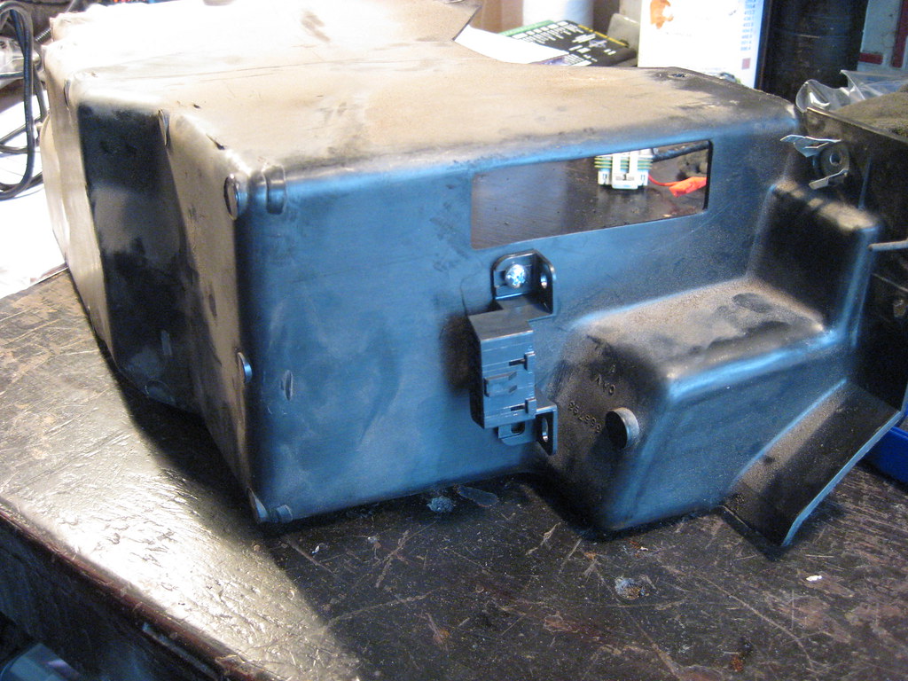
Fortunately there was already a large hole in the glove box so I routed my wires through that. Here I'm finding the alignment of the holes to be drilled. I also mounted the Dakota Digital OBDII box on the back of the glove box which is not shown in the picture below.
This is where I mounted OBDII port. The two screw heads on the back of the glove box is where I mounted the OBDII controller.
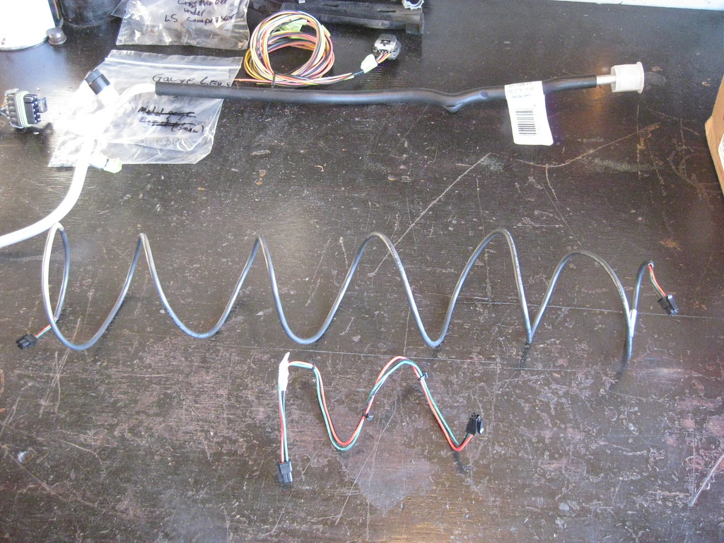
The harness that connects the Dakota Digital brain box to the OBDII controller wasn't long enough so I had to order a longer one.
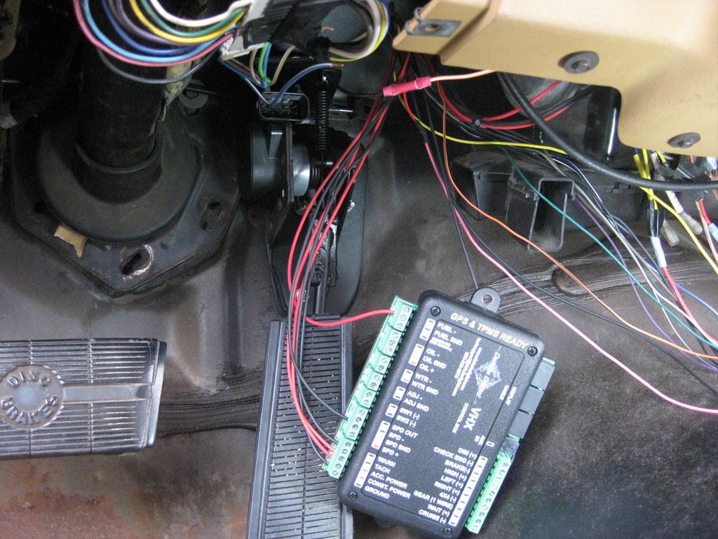
I had previously made a diagram of where each wire should go and used the 1978 Caprice wiring diagrams to determine which wires I needed to splice into, which made finding and hooking everything up much quicker.
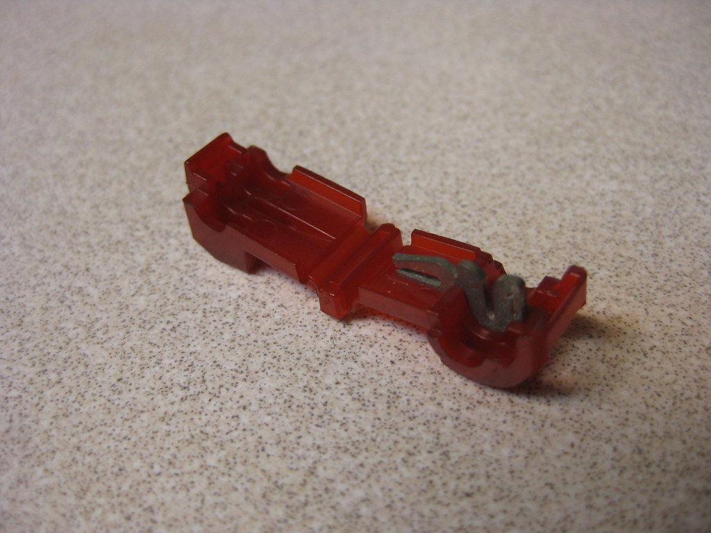
These are T-clamp wire splice connectors. This was the first time I've used them and I really preferred them to the previous kind I had been using. I actually didn't even understand how to use them at first. You just clamp this onto the wire you need to splice into and then insert a blade connector into a small hole in the folded over end, that way you can disconnect the splice if you ever need to.
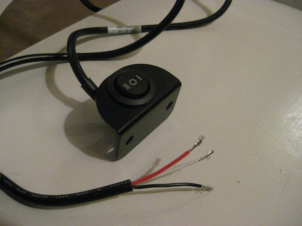
The instructions with the Dakota Digital dash were a bit confusing and caused some delay. In short, Dakota Digital used to provide two push button switches with their units that each had two wires. Now they provide one rocker switch that has three wires and has two functions, up and down. The wiring diagram has been updated to reflect this change, but the written instructions have not, so they were conflicting. Also, Dakota accidentally sent me two separate switches and they were only supposed to send me one, so it was very confusing trying to find out how everything was supposed to be wired. I called the company and we finally worked out the issue.
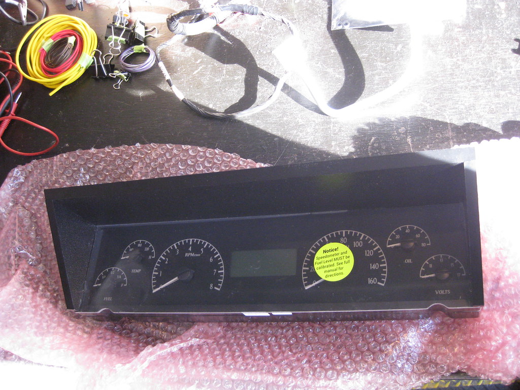
At long last it was time to install the cluster.
There are only two bolts that mount the cluster to the dash so it was a pretty straight forward and easy install. The stock lens installs over the top of what is shown below. My original lens was in poor shape with some of the tabs broken off from various people working on it over the years. Over the Christmas holiday I went up to the farm where I have a parts car in the barn and I got a lens that was in better shape.
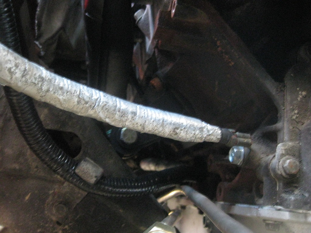
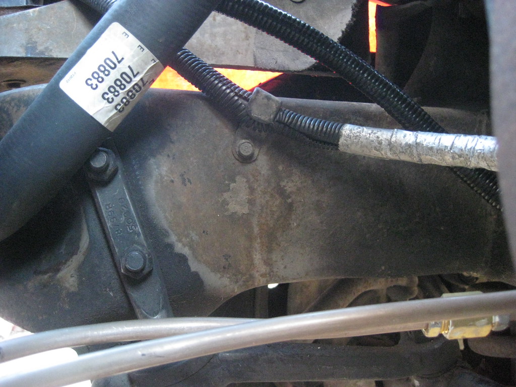
I finished connecting the remainder of the wires. I attached the battery negative cable where the compressor was mounted on the 5.3.
I used some of the original clamps to route the cables.
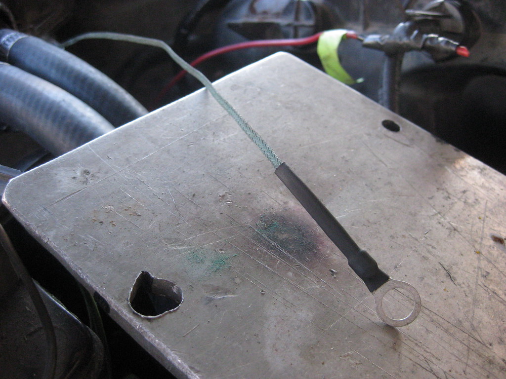
I finally fixed the broken ground strap that came out of the heater core box and I also cleaned up all of the ground mounting locations with a wire brush dremel.
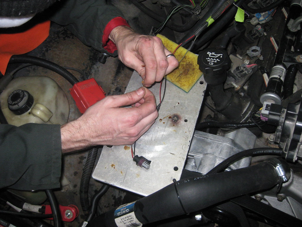
I still had some soldering that needed to be completed on the car. Now that the air intake system was complete I could determine how long the MAF sensor wires needed to be and also some of the wires for the AC sensors and switches. My father-in-law was in town for the Christmas holiday and helped with soldering all the remaining wires on the car.
I got the AC hardline rebent and installed. I had an issue with installing the accumulator and I essentially ruined the threads to the evaporator. I'll most likely have to install a new evaporator and get a new accumulator, but all that will have to wait until after I get the car running.
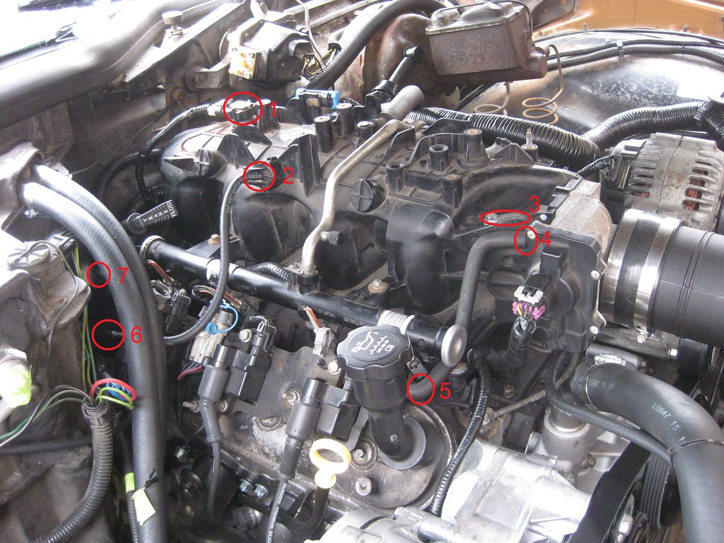
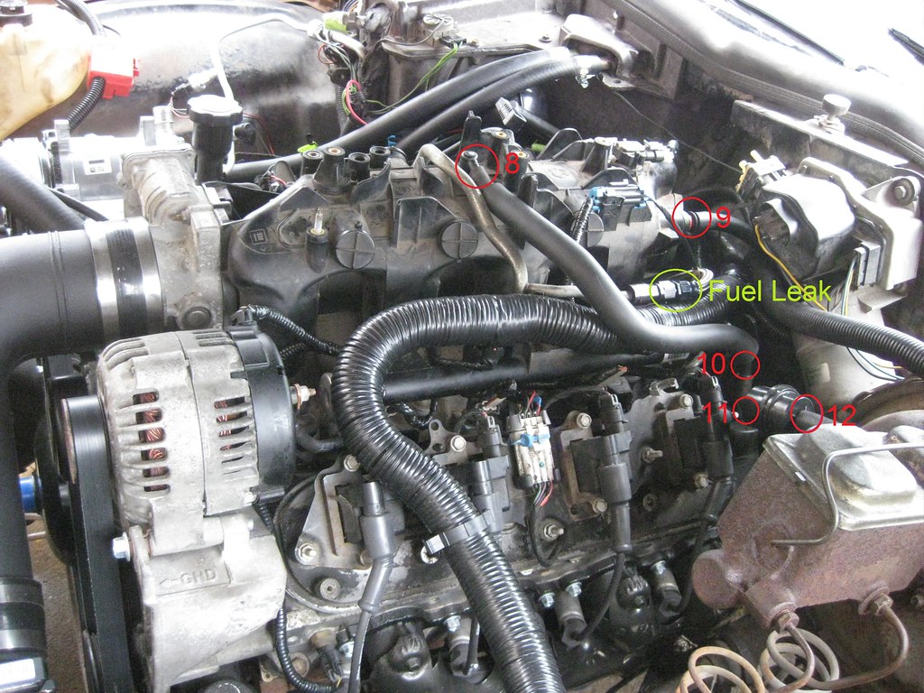
Before I started the car I wanted to get the dash working so I would have gauges to monitor. At first the dash wasn't working but then I later realized I had put some of the fuses in the wrong location. I left some gaps in the fuse locations that can be used to power future relays if I chose to install them. When I put all the fuses in I forgot to include the gaps. I was finally able to start the engine after putting some gas in the tank. I could hear the fuel pump working and the engine didn't crank over very long before it fired up. It is way louder than I wanted so I'll have to take it back and get quieter mufflers put on. When the engine started there was no response from the gas pedal. At the very beginning the engine would idle around 800 rpm, but now idles around 1250 rpm. I was scared at first because when I first start the car it will quickly rev to 2000 rpm and after a couple of tries I found that once it gets to 2000 rpm it will come back down to 1250 or so. I was also getting a code for a MAP sensor. The probable causes for this seem to be a vacuum leak, but I have yet to find a leak. Below are all of the places I've looked to try to find a vacuum leak.
I also had a small fuel leak. I tightened the connector marked below and it so far seems to have eliminated the leak.
I filled the upper radiator hose and then filled the radiator and there appears to be no air left in the cooling system, however the engine slowly overheats. I also noticed after letting the engine run for about two minutes that the exhaust manifolds were glowing red hot. Given the pedal having no response, the glowing manifolds and overheating it seems as though it would be best to have a computer hooked to the computer to see what's going on with the tune before I go further. The PCM is a 2003 Express Van tuned with a 2004 Tahoe tune. With the Holidays here I am somewhat stuck until I can get a tuner hooked up and see what's happening.
